GMV5 D.C INVERTER MULTI VRF SERVICE MANUAL
212
3.2.1.2 Precondition: Units cannot be normally started
Step 1:
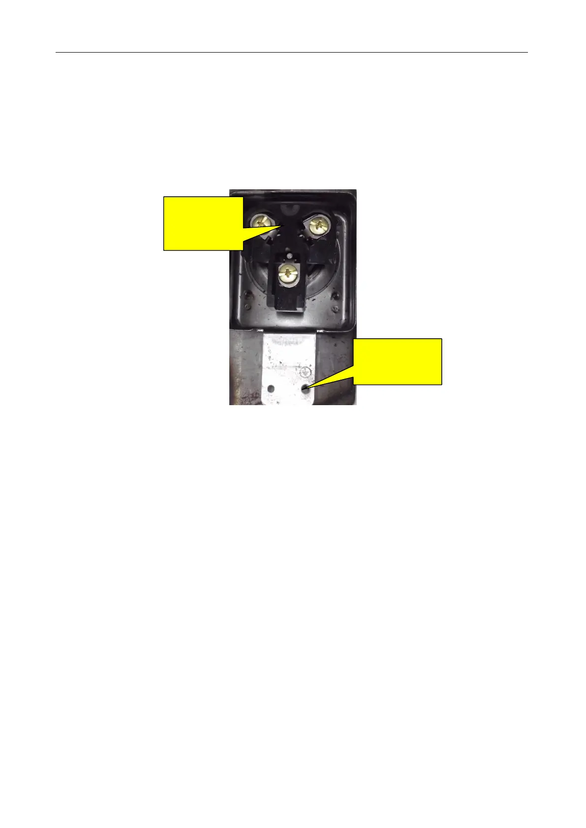
Disconnect the power supply of the units and open the electric junction box of the compressor to
see whether wiring of the compressor is intact.
Step 2:
Measure resistance between two wiring terminals (U, V, W). The resistance value range should be
0.5~2.0 Ω.
Measure the resistance to earth of each wiring terminal. The value should be 10 MΩ. If not, the
compressor has an internal fault.
Step 3:
Check the solenoid valves of the system, include electric expansion valves, oil return valves, and oil
balance valves. Refer to the preceding section for the test method.
Step 4:
Check the IPM module. Refer to the preceding section for the test method
3.2.2 Compressor Replacement (GMV-120WM/B-F(U))
Step 1: Disconnect power supply.
Turn off the power switch of the ODUs and disconnect the line of the power supply and the power
line of the ODUs. Meanwhile, cover the power line with tape for insulation and put a warning sign beside
the power switch to prevent electric shock.
Step 2: Clear electric parts (do not need to disassemble the electric box).
Before removing compressors‘ lines, temperature sensors, and electric heaters, mark them so that
you will reconnect them in a correct manner after clearing. The removed electric box must be covered
and protected from wind and sun.
After the box is removed, take care with the removal of electric parts‘ lines. DO NOT pull the lines
with excessive force; or they may be broken. The removed electric box must be protected for dustproof
and waterproof purposes.
Measure
resistance
between two
wiring terminals
using a multimeter
Measure the
resistance to earth of
each wiring terminal
one after another
 Loading...
