GMV5 D.C INVERTER MULTI VRF SERVICE MANUAL
234
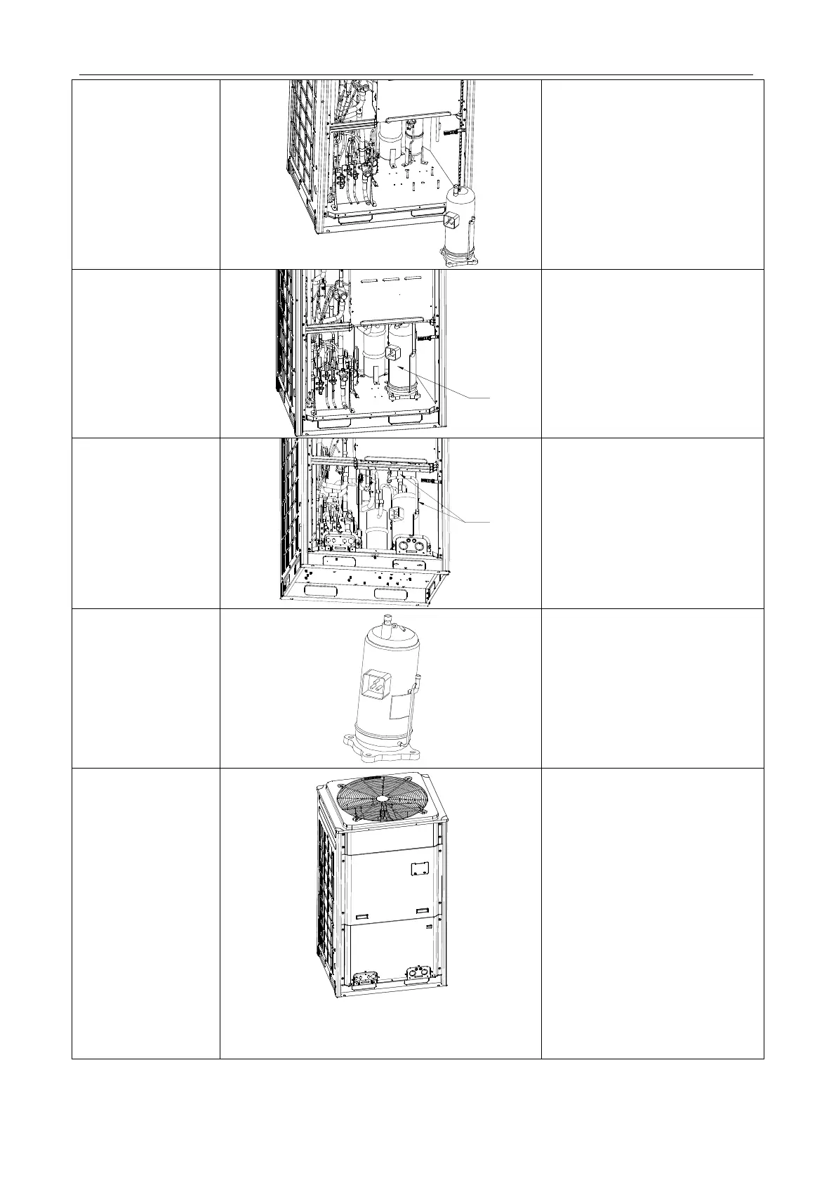
5. Remove the
compressor.
●
Remove the compressor from the
chassis.
6. Install a new
compressor on the
chassis.
●
Put the compressor in a proper
position.
●
Use a wrench to screw the nuts on
the compressor.
●
The compressor should not be
installed upside down.
7. Connect the suction
and discharge pipes of
the compressor to the
pipeline system.
●
Heat the
suction and discharge
pipes by acetylene welding and then
install the pipes.
●
During welding, charge nitrogen
into the pipes. The pressure should
be controlled within 0.5±0.1 kgf/cm
2
(relative pressure).
●
Avoid nearby materials from being
burnt during welding.
8. Connect the power
line to the compressor,
and install the electric
heating belt, top
temperature sensor,
and discharge air
temperature sensor.
●Put the power line in a proper
position.
●
Use a screwdriver to screw the
power line.
●
Install the electric heating belt,
top
temperature sensor, and discharge
air temperature sensor
.
●
Put the sound-proof sponge back to
position.
9. Check and then
install the front panels.
●
Check various parts and connecting
lines.
●
If no problem is found, hook the
front panels and tighten the screws.
 Loading...
