GMV5 D.C INVERTER MULTI VRF SERVICE MANUAL
60
Ensure sufficient rigidity for the devices. Take anticorrosive measures for exposed part of built-in
fittings. If the foundation must be waterproof, takes waterproof measures.
(3) Construction of steel casings
Equip a steel casing for all pipes which are led through the wall or floor. Pipe welding joints cannot
be placed inside the sleeve. The steel casing must be parallel with the bottom of the wall or floor but be
20 mm(0.8inch) or more above the bottom. The diameter of the steel casing must be determined based
on the thickness of the insulation layer and the inclination degree of the condensate water pipe. Fill the
gap between the pipe and the sleeve with flexible and non-flammable materials. The sleeve cannot be
used as a support point of the pipe.
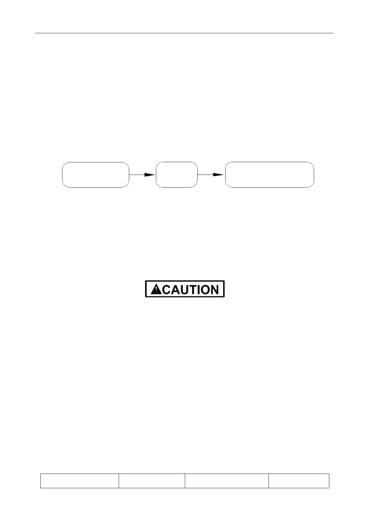
(4) Operation Sequence
Drawing of built-
in metal fittings
Making
ink lines
Installing built-in
metal fittings
If possible, make ink lines on the ground and project them to the top of the building.
(5) Installing Built-in Metal Fittings
Select built-in metal fittings in accordance with local regulations.
(6) Installing Expansion Bolts
Use expansion bolts when built-in metal fittings are unavailable due to design change.
If the foot pedal is 2 m (6.5feets) or more from the ground, there must be three points of
support.
The foot pedal must be tightened securely with the ladder.
Do not perform operations on the top of the ladder.
6.1.3.3 Shaping and Fixing of Pipes
When installing refrigerant pipes, ensure that the directions and branches are correct with minimum
length. Use minimum number of braze welding junctions and elbows. Alignment and insulation after
installation cannot affect the pipe location and elevation. There shall not be flat bending or corrugation
on the pipe after piping.
Use angle steel support, bracket, round steel hanger, U-type pipe clip, or flat steel to fix pipes
outside the insulation layer. It is better that the insulation materials be not compressed to ensure good
insulation.
The style and workmanship of supports, hangers, and brackets must follow the HVAC Systems
Design Handbook.
The minimum distance between supports, hangers, and brackets is listed in the table below:
External Diameter of the
Pipe mm(inch)
 Loading...
