GMV DC Inverter VRF
41
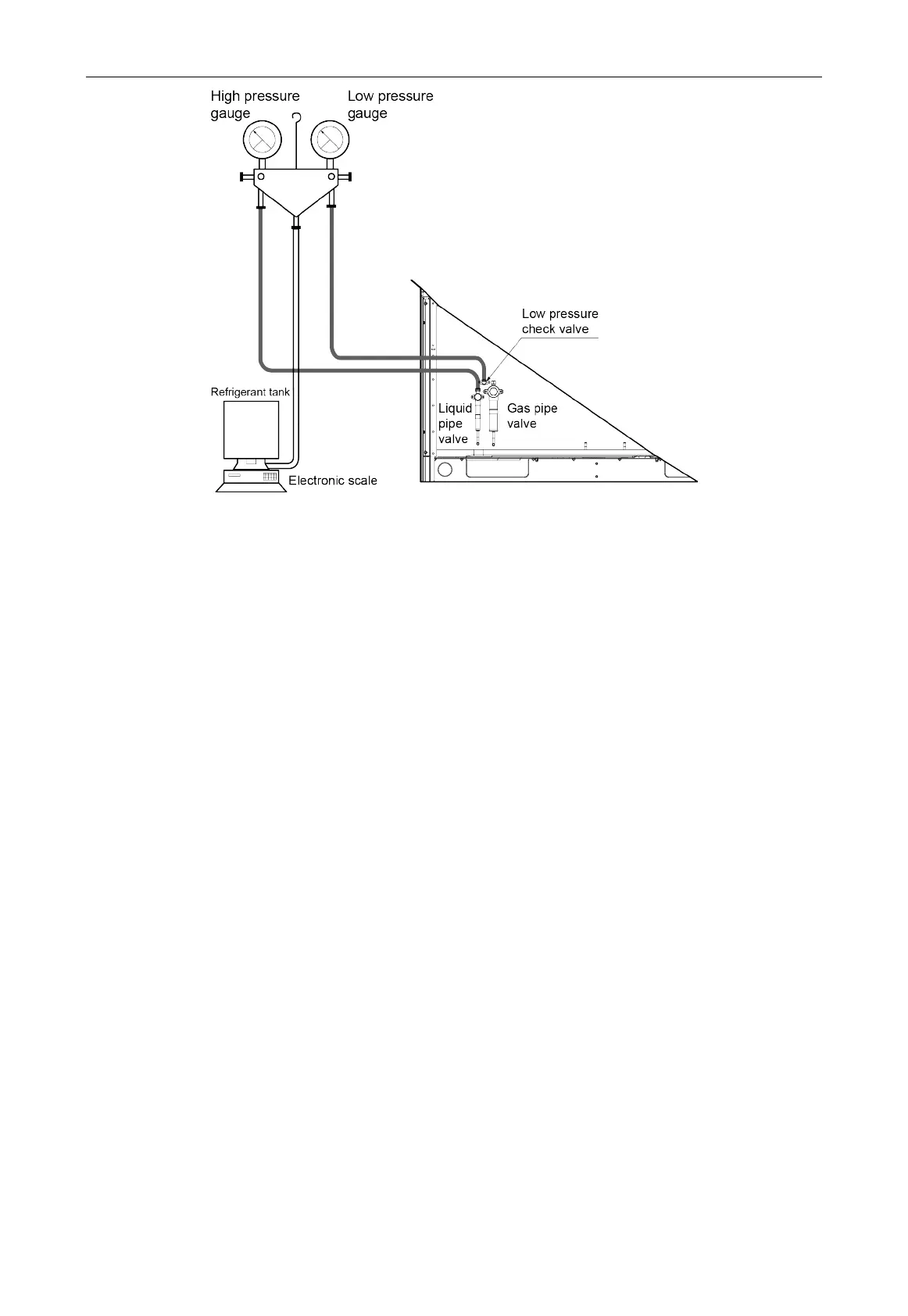
Fig. 3.7.3
Step 2: Fully open the liquid pipe valve and gas pipe valve of each module.
Step 3: Make the complete unit enter into debugging operation by the debugging software or the
main board of outdoor unit. (see the debugging part for the specific operation).
Step 4: When it comes to the procedure of charging refrigerant, open the refrigerant tank valve
and charge the residual refrigerant “m”.
Step 5: When all refrigerant has been charged, close the refrigerant tank valve and wait until the
automatic debugging for the complete unit is finished.
Step 6: Once debugging is finished, disassemble the pressure gauge, etc., to complete the
refrigerant-charging work.
3.7.3 Precautions on Refrigerant Leakage
(1) Personnel related to air conditioning engineering design and installation operators must
abide by the safety requirement for preventing refrigerant leakage specified in local laws and
regulations.
(2) Multi VRF unit adopts R410A refrigerant. When the unit is installed in the place where there
are people, the refrigerant must not exceed the maximum allowable concentration.
Otherwise, people involved can be stifled by the refrigerant. For example the maximum
allowed concentration level of refrigerant to a humanly space for R410A according to the
appropriate European Standard is limited to 0.44 kg/m
3
.
The maximum amount of refrigerant(kg)in the system = The volume of the room (m
3
) ×The
maximum allowed concentration level of refrigerant (kg/m
3
)
Total amount of refrigerant (kg) in the system = Total additional charging amount (kg) + Amount
of refrigerant (kg) which is charged before leaving the factory (for the system consisting of multiple
modules in parallel, the accumulative charge quantity of modules before leaving the factory is used)
Total amount of refrigerant (kg) in the system ≤ the maximum amount of refrigerant (kg) in the
system
 Loading...