DC Inverter Multi
VRF Service Manual
21
CONTROL
C. 485 communication interface: indoor unit communication network and adaptor board CN1 shall be connected
to the mainboard of indoor unit through 2-core (3-core pin header) communication cable; drive communication network
and the mainboards CN11~CN14 of outdoor unit shall be connected to the drive board through 2-core (3-core pin header)
communication cable.
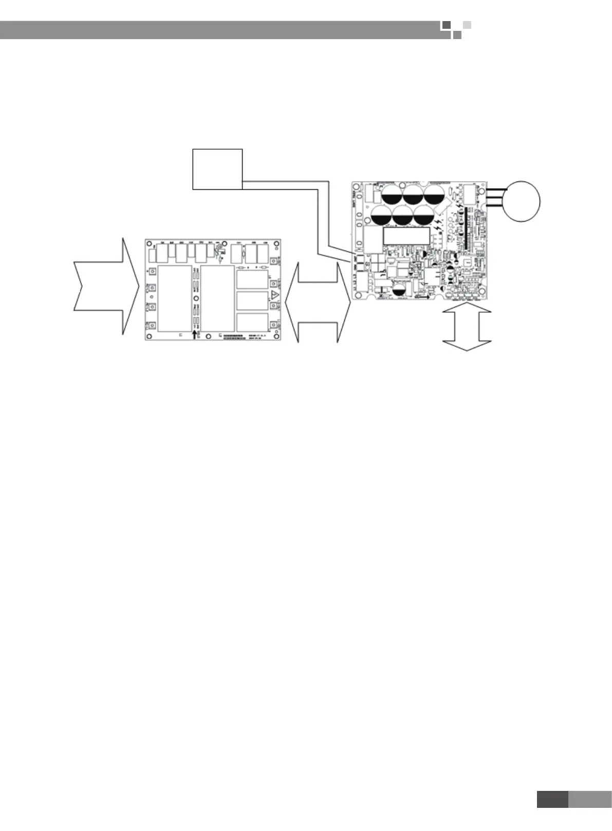
2) Drive control system
3-phase power supply unit
L1,L2,
L3,N
L1,L2,
L3,N
Reactor
Communication
M
Functions of various modules:
A Filter plate: one of the two key functions is to lter and eliminate power interferences and ensure anti-interference
capability of the unit even in a rugged power supply environment; the other one is to suppress interferences from power
supply in order to prevent the operation of the unit from affecting other appliances such as TV. Because inverter unit works
in a special way that is relatively sensitive to interferences, lter plate is normally arranged. Because 3-phase power supply
is used for the unit, 3-phase lter plate that uses 3-stage ltering mode shall be employed. Input terminals of 3-phase lter
plate are respectively AC-L1, AC-L2,AC-L3 and N, and corresponding output terminals are respectively L1-OUT,L2-OUT,
L3-OUT and N-OUT.
B Drive board is a key part of control system. Receiving commands from the main control board, the drive board
can transform 380V, 50Hz, 3-phase commercial power into AC power with adjustable amplitude and frequency, capable to
drive compressor.
 Loading...