126
10
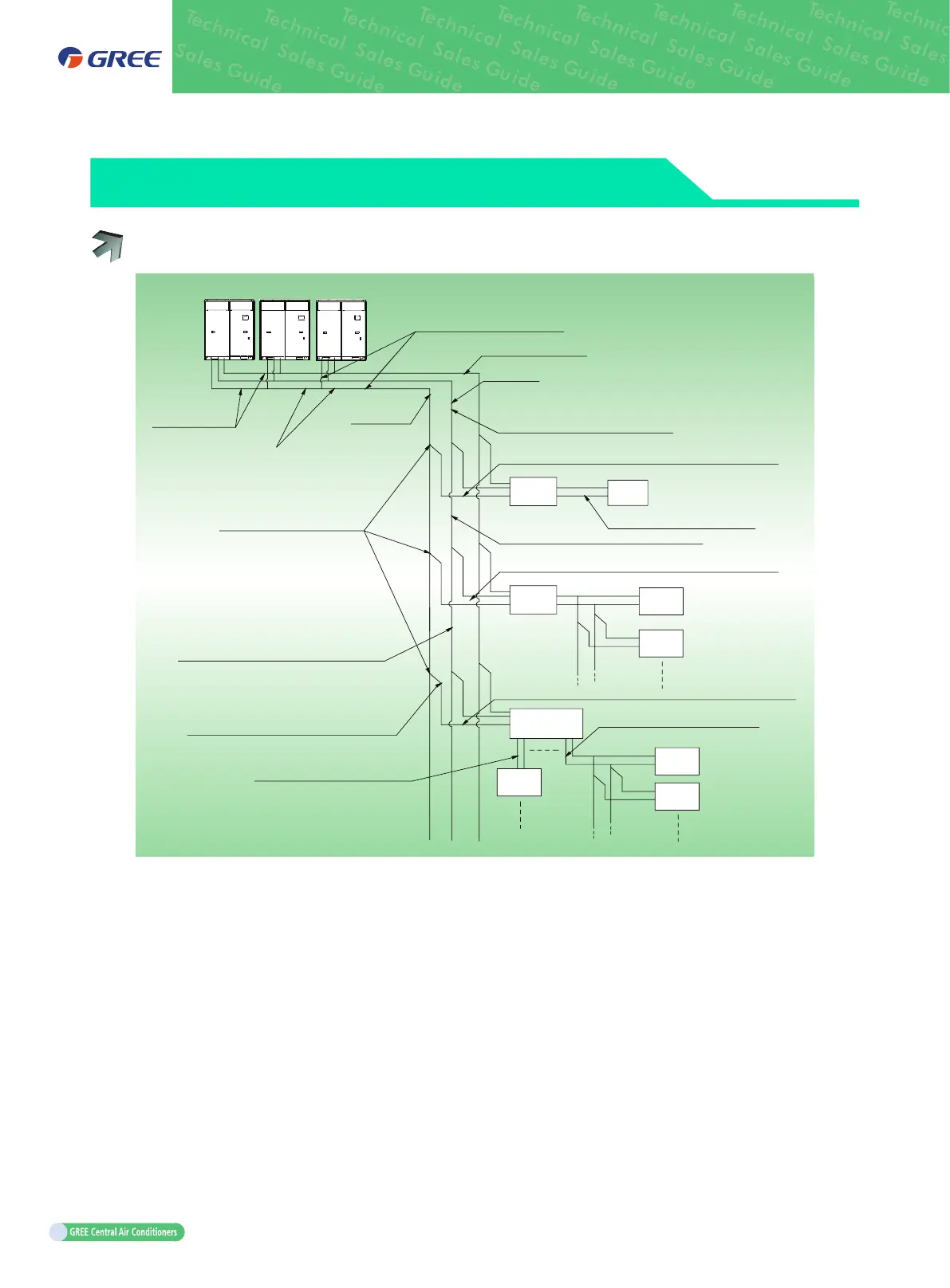
MODEL SELECTION FOR UNIT PIPING
10.1 Schematic Diagram of Piping Connection
Branch between outdoor units
High pressure gas pipe
Liquid pipe
Outdoor
connection pipe
Connection pipe between outdoor branchs
Low pressure
gas pipe
Branch between indoor units
Connection pipe between outdoor
branch and the first indoor branch
Connection pipe between indoor branch and indoor units
Mode
exchanger
Mode
exchanger
Mode
exchanger
Indoor
unit 1
Indoor
unit 2
Indoor
unit 3
Indoor
unit 4
Indoor
unit 5
Indoor
unit 6
Connection pipe between mode
exchanger and indoor units
Connection pipe between indoor branchs
Connection pipe between indoor branch and mode exchanger
Connection pipe between mode
exchanger and indoor branch
Connection pipe between indoor branchs
Connection pipe between indoor branchs
Connection pipe between
mode exchanger and indoor units
Connection pipe between indoor branch and indoor units
ModuleModule
1
ModuleModule
2
ModuleModule
3

 Loading...

