135
GMV5 HR HEAT RECOVERY
VRF Units Technical Sales Guide
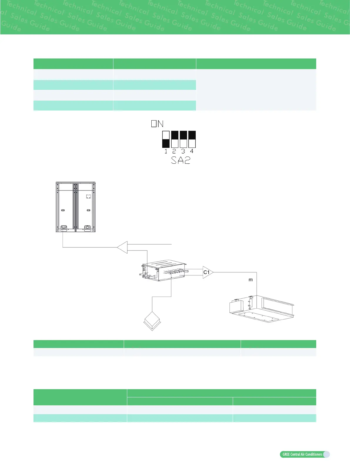
Parallel connection
Indoor unit Communication connection
for mode exchanger
Remarks
Indoor unit No.1 and No.2 “1D1 1D2”
Parallel connection can be conducted only as the
combination of this table, it is not allowed to otherwise
connect. Note that after the connection, manually set
the SA2 dial code of corresponding mainboard, and
dial the code in the rst place to number end.
Indoor unit No.3 and No.4 “3D1 3D2”
Indoor unit No.5 and No.6 “5D1 5D2”
Indoor unit No.7 and No.8 “7D1 7D2”
Connecting method is as shown in follown Fig
.
10.5.1 Branch selection of indoor unit of mode exchanger (“C1”)
R410A refrigerant system capacity of down steam indoor units: X (Btu/h) Model
Y-type branch 48500<X≤96000 FQ01B/A
10.5.2 Piping size between mode exchanger and downstream indoor unit (“m”)
Size of connection pipe between indoor branch and indoor unit should be consistent with the connection
pipe of indoor unit.
Piping between indoor branch and indoor unit “m”.
Rated capacity of indoor units
(Btu/h)
Size of connection pipe between indoor branch and indoor unit
Gas pipe mm(in.) Liquid pipe mm(in.)
48500<C≤72000
Φ
19.05(3/4)
Φ
9.52(3/8)
72000<C≤96000
Φ
22.2(7/8)
Φ
9.52(3/8)

 Loading...

