37
GMV5 HR HEAT RECOVERY
VRF Units Technical Sales Guide
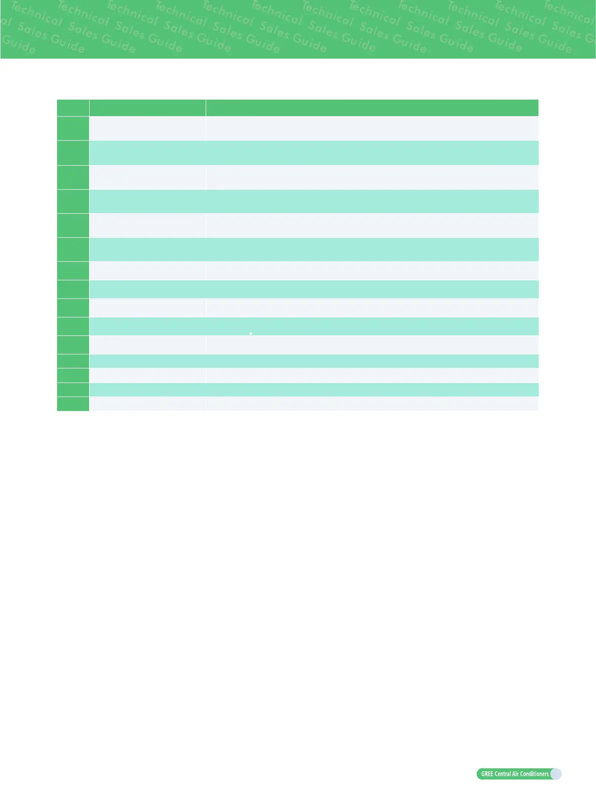
No. Name Main Function
28 Drain valve for cooling Drainage control valve for cooling of refrigerant adjustment tank
29 Drain valve for heating Drainage control valve for heating of refrigerant adjustment tank
30 Dry strainer
Avoid impurities getting into the electric parts. Meanwhile, absorb the water inside the
liquid status to prevent ice blockage.
31 Filter Prevents impurities from entering components and parts.
32 Capillary tube Supports ow regulating and pressure reduction.
33 One-way valve
Prevent refrigerant backow into liquid pipe when the pressure inside the refrigerant
adjustment tanks is too high.
34 One-way valve
Prevent the refrigerant inside the liquid valve ow into the refrigerant adjustment tank from
heating drain valve.
35 Liquid valve
Stop valve, closed when the unit is delivered from the factory and will be opened after
installation.
36 Low pressure gas pipe valve
Stop valve, closed when the unit is delivered from the factory and will be opened after
installation.
37 High pressure gas pipe valve
Stop valve, closed when the unit is delivered from the factory and will be opened after
installation.
38
Low-pressure measurement
valve
Detects the low pressure value or charges refrigerant during system running.
39 Unloading valve Opening if the pressure inside the liquid pipe is too high
40 Oil return solenoid valve Oil return control for the compressor
41 Gas-bypass valve Make sure pressure of the system is balanced
42 Pressure-balanced valve Ensures success startup of compressor.
.

 Loading...

