Do you have a question about the Gree GPC07AH-K3NNC3D and is the answer not in the manual?
Electrical connection diagrams showing wire colors, terminals, and component layout.
Layouts of the main board and display board silk screens with component references.
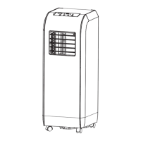
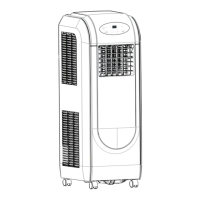
Explanation of the unit's front panel controls, indicators, and button functions.
Details on remote controller buttons, icon display, and operation modes.
Explanation of operating modes like Cool, Dry, Fan, Auto, and their conditions.
Critical safety instructions to follow before and during installation and maintenance.
Specific safety rules related to electrical work, grounding, and wiring.
Guidelines for safe handling and usage of refrigerants.
Procedure for correctly attaching the drainage pipe for condensate removal.
Instructions for installing the window frame kit to vent the unit.
Steps for connecting and removing the heat discharge pipe.
Procedure for verifying the unit's functionality after installation.
Explanation of how the unit handles condensate water drainage.
Instructions for cleaning the unit's exterior, filter, and heat-removal pipe.
Table listing error codes, display methods, A/C status, and possible causes.
Flowcharts guiding the diagnosis and resolution of common malfunctions.
Detailed troubleshooting methods for common issues like starting problems and poor cooling.
Procedure to remove the remote controller housing from the unit.
Steps to detach the air filter assembly from the unit.
Instructions for removing the front panel assembly of the unit.
Procedure to detach and remove the rear panel of the unit.
Steps for removing the left and right side panels of the unit.
Procedure to remove the cover of the electrical box.
Steps to remove the main electrical box assembly.
Procedure to remove a facing bar component.
Steps to remove the volute cover for fan access.
Instructions for removing the evaporator assembly, including desoldering.
Procedure to remove a second facing bar component.
Steps to remove the first facing bar.
Procedure for removing the duct assembly.
Steps to remove connecting rods and vertical louvers.
Procedure to remove the upper volute and mesh enclosure.
Steps to remove the upper centrifugal louver.
Procedure to remove the lower volute and water tray.
Steps to remove the diversion ring.
Procedure to remove the lower centrifugal louver.
Steps to remove the fan motor.
Procedure to remove the water retaining tray.
Instructions for removing the condenser assembly, including desoldering.
Steps to remove the compressor assembly.
Procedures for removing motor sub-assembly, water level switch, and caster wheels.
| Brand | Gree |
|---|---|
| Model | GPC07AH-K3NNC3D |
| Category | Air Conditioner |
| Language | English |