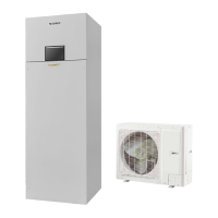
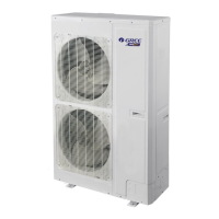
Unit Control
2.2 Operation Conditions
Capacities and power inputs are based on the following conditions (floor heating /cooling )
Indoor Water Temp 23°C/18°C;
Indoor Water Temp 30°C/35°C;
Outdoor Air Temp 35°C DB/24°C WB
Outdoor Air Temp 7°C DB/6°C WB
Capacities and power inputs are based on the following conditions (FCU or radiator)
Indoor Water Temp 12°C/7°C;
Indoor Water Temp 40°C/45°C;
Outdoor Air Temp 35°C DB/24°C WB
Outdoor Air Temp 7°C DB/6°C WB
2.3 Flowchart of Model Selection
2.4 Design Principle
Cooling: capacity of the unit ≥ cooling load of the air conditioning
Heating: capacity of the unit ≥ max{ heating load, floor heating load, water heating load}
Water Tank: it should be selected based on the sanitary outfit or quantity of users. Each unit
can accommodate only one water tank.
3 Selection of the Underfloor Coils
3.1 Calculation of Unit Load for Floor Heating
Empirical Values of Floor Heating Load Per Square Meter

 Loading...


