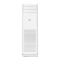
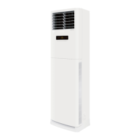
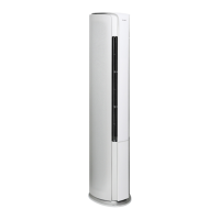
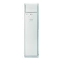
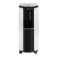
66
Installation and Maintenance
Service Manual
Some models may not contain some parts, please refer to the actual product.
NO. Description
1 Right Side Plate Sub-Assy
2 Rear Plate Sub-Assy
3 Right Air Guard
4 Top Cover Sub-Assy
5 Left Air Guard
6 Left Side Plate Sub-Assy
7 Evaporator Assy
8 Air Guard Assy
9 Chassis
10 Wire Clamp
11 Fan Motor
12 Water Tray Sub-Assy
13 Breakwater Sub-Assy
14 Protection Cover
15 Remote Control Panel Sub-assy
16 Propeller Housing Sub-assy
17 Centrifugal Fan
18 Diversion Circle
19 Gasket
20 Electric Box Cover Sub-Assy
21 Electric Box Assy
22 Main Board
NO. Description
23 Terminal Board
24 Motor Cover
25 SteppingMotor
26 Air Guide Bushing
27 Guide Blade Lever
28 SteppingMotor
29 Crank 1
30 Air Louver 1
31 Air Louver 2
32 Guide Louver
33 Crankshaft of Guide Louver
34 Air Outlet Panel Assy
35 Display Sub-Assy
36 Display Board
37 Remote Controller
38 Screw Cover
39 Air Intake Panel Assy
40 Filter (lower)
41 Filter Sub-assy(Upper)
42 Connecting Cable
43 Connecting Cable
44 Detecting Plate
 Loading...
