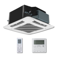
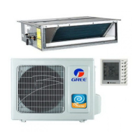
GREE Duct type Ducted Type Split Air-Conditioner Units
77
Instruction:
(1) Indicator of main board (digital display tube) “LED1” and four button: “SW1”, “SW2”, “SW3” and
“SW4”:
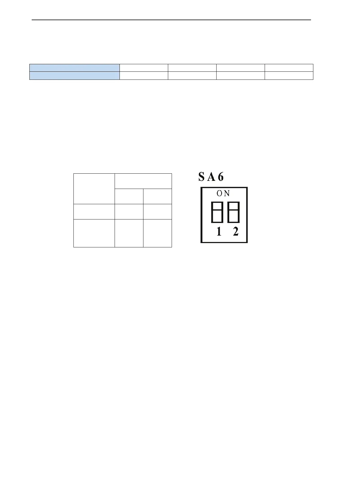
(2) “JUMP1”: jumper cap of the unit. Jumper cap No. varies from different type of unit.
(3) DIP switch “SA1”, DIP switch varies from different cooling capcity, before leaving the factory,
DIP switch is set for different models and fixed with glue.
(4) The main control function DIP switch “SA6” is used to set master module and subsidiary
module, the defaulted factory setting is the main module. As the fig is shown, dialing to “ON”
side represents “0” and dialing to the figure side represents “1”, the defaulted setting for the unit
is “00”. For the system with two outdoor units, one of them shall be set as the main module,
namely, dial “SA6” to “00”, then set the other unit as subsidiary module, namely, dial the “SA6”
to “10”.
Function
SA6
1 2
Master module 0 0
Subsidiary
module
1
0
1.4.3 Basic Operation of Project Debugging
(1) Start project debugging
Press “SW3” button consecutively in the master module for over 5s to enter auto debugging.
(2) Exit project debugging
After entering project debugging, press “SW3” button consecutively in the master module for
over 5s to exit the debugging.
(3) Complete project debugging
After entering project debugging and completing step “04”, press “SW2” and “SW3” button
consecutively in the master module for over 5s to exit the debugging, then the system can
operate normally.
Flow-process diagram of debugging:
 Loading...