For proper unit function and safety, follow everything in this startup procedure in the order presented. This is to
be done after the electrical connections are complete.
Special Tools Required • Volt meter
• Incline manometer or equivalent
• Tachometer
• Amperage meter
1. General
Check all fasteners and set screws for tightness. This is especially important for bearings and fan wheels.
Also, if dampers are not motorized, check that they open and close without binding.
SYSTEM STARTUP
**WARNING**
DO NOT OPERATE ENERGY RECOVERY VENTILATOR WITHOUT THE FILTERS AND BIRDSCREENS INSTALLED.
THEY PREVENT THE ENTRY OF FOREIGN OBJECTS SUCH AS LEAVES, BIRDS, ETC.
DO NOT REMOVE ACCESS PANELS OR OTHER COMPONENTS WHILE STANDING ON A LADDER OR OTHER
UNSTEADY BASE. ACCESS PANELS AND COMPONENTS ARE HEAVY AND SERIOUS INJURY MAY OCCUR.
12
2. Check Voltage
Before starting the unit compare the supplied voltage with the unit’s nameplate voltage and the motor
voltage.
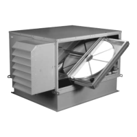
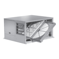
3. Energy Recovery Wheel
First, follow the instructions on page 16 for
pulling the energy recovery cassette halfway
out of the unit.
DRIVE BELT
Turn the energy recovery wheel by hand to verify
free operation. Inspect the belt, which drives the
energy wheel rotation. Make sure the belt rides
smoothly through the pulley and over the wheel
rim.
AIR SEALS
Turn the energy recovery wheel by hand to verify
free operation. Check that the air seals, located
around the outside of the wheel and across the
center (both sides of wheel), are secure and in
good condition.
Air seals which are too tight will prevent proper
rotation of the energy recovery wheel. Recheck
the air seals for tightness. Air seal clearance may
be checked by placing a sheet of paper, like a
feeler gauge, against the wheel face. To adjust the
air seals, loosen all eight seal retaining screws.
These screws are located on the bearing support
that spans the length of the cassette through the
wheel center. Tighten the screws so the air seals tug slightly on the sheet of paper as the wheel is turned.
Replace cassette into unit, plug in wheel drive, replace access door and apply power. Observe that the
wheel rotates freely. If wheel does not rotate or is binding, remove the cassette (instruction on page 16).
FIGURE 5
Drive Belt
Drive Pulley
Adjustable
Air Seals
Label showing
cassette serial no.
and date code