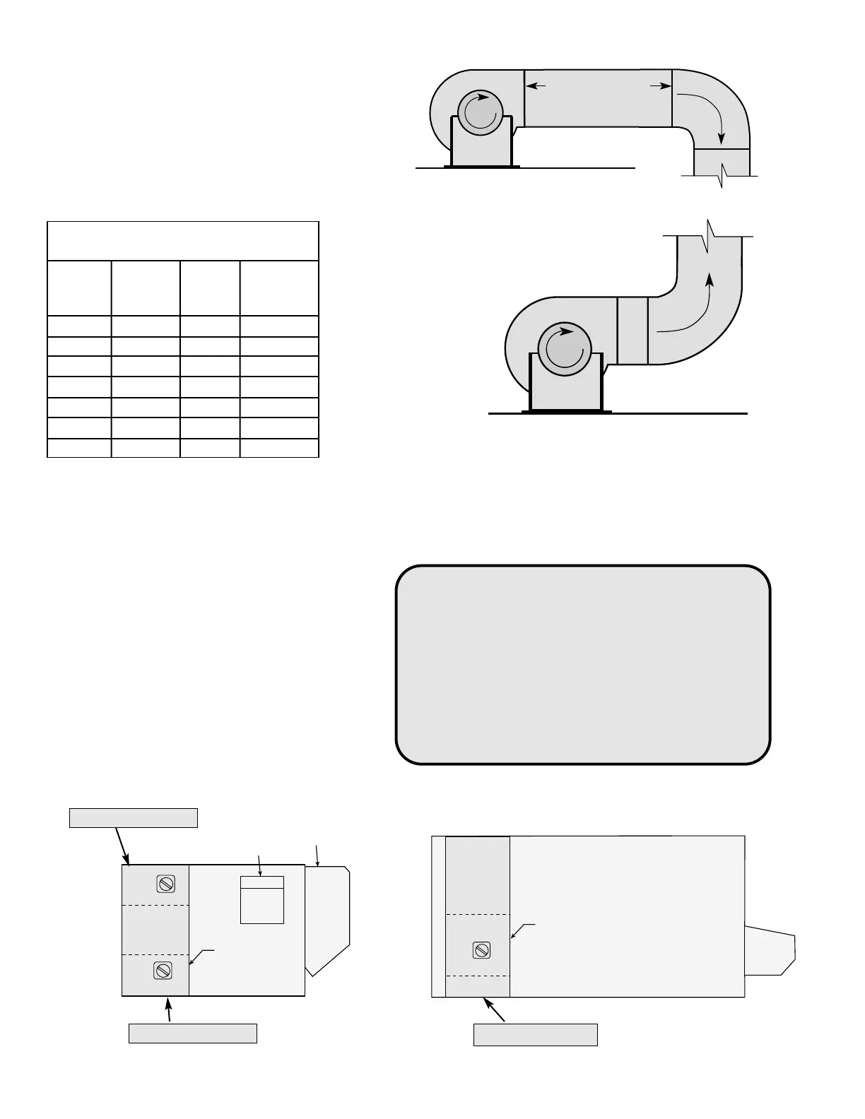
FIGURE 3
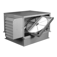
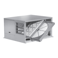
WEATHERHOODS (Arrangement B, C and D)
The outdoor air intake weatherhood is shipped factory assembled and mounted to the ERV. The exhaust
discharge weatherhood is fastened to the skid and shipped with the ERV unit.
DUCT WORK CONNECTIONS
Examples of good and poor fan-to-duct
connections are shown in Figure 3. Air flow
out of the fan should be directed straight or
curve the same direction as the fan wheel
rotates. Poor duct installation will result in low
airflow, increased noise levels and other
system effects.
INSTALLATION (continued)
6
Recommended Discharge
Duct Size and Length
ERV
ERV
Duct
Straight
Model
Blower
Size
Duct
Size Length
251 10 9 x 9 40
361 10 14 x 14 40
521 12 20 x 20 48
581 15 28 x 28 60
522S 15 28 x 28 60
522H 18 32 x 32 72
582 20 34 x 34 80
ELECTRICAL CONNECTIONS
CAUTION !
If any of the original wire must be replaced,
the replacement wire must have a temperature
rating of at least 105°C, except for energy cut-off
or sensor lead wire which must be 150°C.
DANGER !
High voltage electrical input is required for this
equipment. This work should be performed by a
qualified electrician.
Before connecting power to the unit, read and
understand the following instructions and
wiring diagrams. Complete wiring diagrams are
attached inside the door(s) of the unit.
All wiring should be done in accordance with
the National Electrical Code ANSI/NFPA 70-
latest edition and any local codes that may
apply. In Canada, wiring should be done in
accordance with the Canadian Electrical Code.
The equipment must be properly grounded.
FIGURE 4
All dimensions shown are in inches.