EasyManua.ls Logo

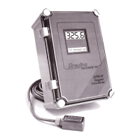
Greyline Instruments DFM-IV User Manual

Greyline Instruments DFM-IV
44 pages
To Next Page IconTo Next Page
Page #1 background imageLoading...
Page #1 background image
USER’S GUIDE
Installation & Operation
Instructions
Doppler Flow Meter
Model DFM-IV
Manual Series A.6

Questions and Answers:

Greyline Instruments DFM-IV Specifications

General IconGeneral
BrandGreyline Instruments
ModelDFM-IV
CategoryMeasuring Instruments
LanguageEnglish

Summary

QUICK BENCH TEST

CONNECTIONS

Details power input requirements (115VAC/230VAC) and notes on electrical safety compliance.

KEYPAD SYSTEM

MENU - FLOW CHART

Illustrates the DFM-IV menu system navigation and how to store calibration values.

RUN

TOTALIZER

Explains how to access, view, and reset the totalizer value for accumulated flow volume.

SIGNAL STRENGTH

Details how to adjust signal strength for optimal flow meter performance and ensure signal penetration.

Relays 1 2 3 (Relay Status Display)

24 HR LOG

Mentions the 24 HR LOG menu available for flow meters equipped with an optional Data Logger.

PASSWORD

Describes the password system to prevent unauthorized access to the calibration menu.

UNITS/MODE

Explains how to select units (e.g., ft, in, m) and operating modes (Flow or Velocity).

CALIBRATION

4-20mA CURRENT LOOP

Explains how to offset the 4-20mA output to correspond to specific flow rates.

DAMPING

Describes how to adjust damping to stabilize readings under turbulent flow conditions.

RELAY PARAMETERS

SPECIAL FUNCTIONS

SENSOR MOUNTING LOCATION

SENSOR MOUNTING

SENSOR COUPLING

SENSOR MOUNTING/COUPLING RECOMMENDATIONS

ENCLOSURE INSTALLATION

SYNCHRONIZATION

BACKFLOW REJECTION

ERROR/WARNING MESSAGES

FUSE REPLACEMENT

Provides step-by-step instructions for replacing the fuse within the power module.

FIELD TROUBLESHOOTING (METER READING LOWER THAN EXPECTED)

FIELD TROUBLESHOOTING (METER READING ERRATIC / NO FLOW INDICATION)

FIELD TROUBLESHOOTING (METER READING TOO HIGH / DOES NOT TRACK FLOW)

COMMON QUESTIONS AND ANSWERS (PIPE VIBRATION, NOISE, CORROSION)

COMMON QUESTIONS AND ANSWERS (SIGNAL STRENGTH, CABLE LENGTH, RECALIBRATION)

APPLICATIONS HOTLINE

PRODUCT RETURN PROCEDURE

Outlines the procedure for returning instruments for service or warranty repair, including required information.

FLOW METER DATA SHEET

LIMITED WARRANTY

APPENDIX A – OPTIONS

SENSOR INTRINSIC SAFETY (OPTION 2ISB)

ENCLOSURE HEATER AND THERMOSTAT - Option TH

ENCLOSURE SUNSCREEN - Option SCR

Describes the optional sunscreen to protect electronics from overheating and condensation caused by sunlight.

POWER INPUT OPTION 12VDC OR 24VDC

QUICK BENCH TEST (12/24VDC)

Details how to perform a quick bench test for models configured with 12VDC or 24VDC power input.

CONNECTIONS (12/24VDC)

Explains power input connections for 12VDC/24VDC models and essential grounding requirements.

INSERTION FLOW SENSOR (OPTION ISE)

HIGH TEMPERATURE SENSOR (OPTION SE3H)

Details the high-temperature sensor, its mounting requirements, and operational specifications.

Data Logger Menu (Optional)

DATA LOGGING (Optional) - Setup

DATA LOGGING (Optional) - Log Management

DATA LOGGING (Optional) - Trend Logging Modes

DATA LOGGING (Optional) - Session Management

RS232C SERIAL OUTPUT (with optional Data Logger)

RS485 SERIAL OUTPUT

SPECIFICATIONS (Enclosure & SE3 Sensor)

APPENDIX B - CONVERSION TABLE

PIPE CHARTS (Carbon Steel & PVC)

PIPE CHARTS (Stainless Steel, Hastelloy, Titanium)

Tables detailing pipe dimensions for Stainless Steel, Hastelloy 'C', and Titanium pipes across different schedules.

PIPE CHARTS (Cast Iron)

Tables detailing pipe dimensions for Cast Iron pipes according to ASA and AWWA standards.

DFM-IV CALIBRATION RECORD

Related product manuals