BdYZa<&%%+$<&%%,B[\#H^cXZ.$%.
"("
To reduce the risk of
serious injury when using
this machine, read and
understand this entire
manual before beginning
any operations.
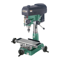
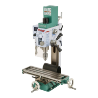
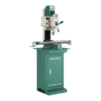
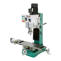
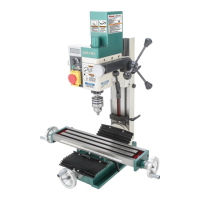
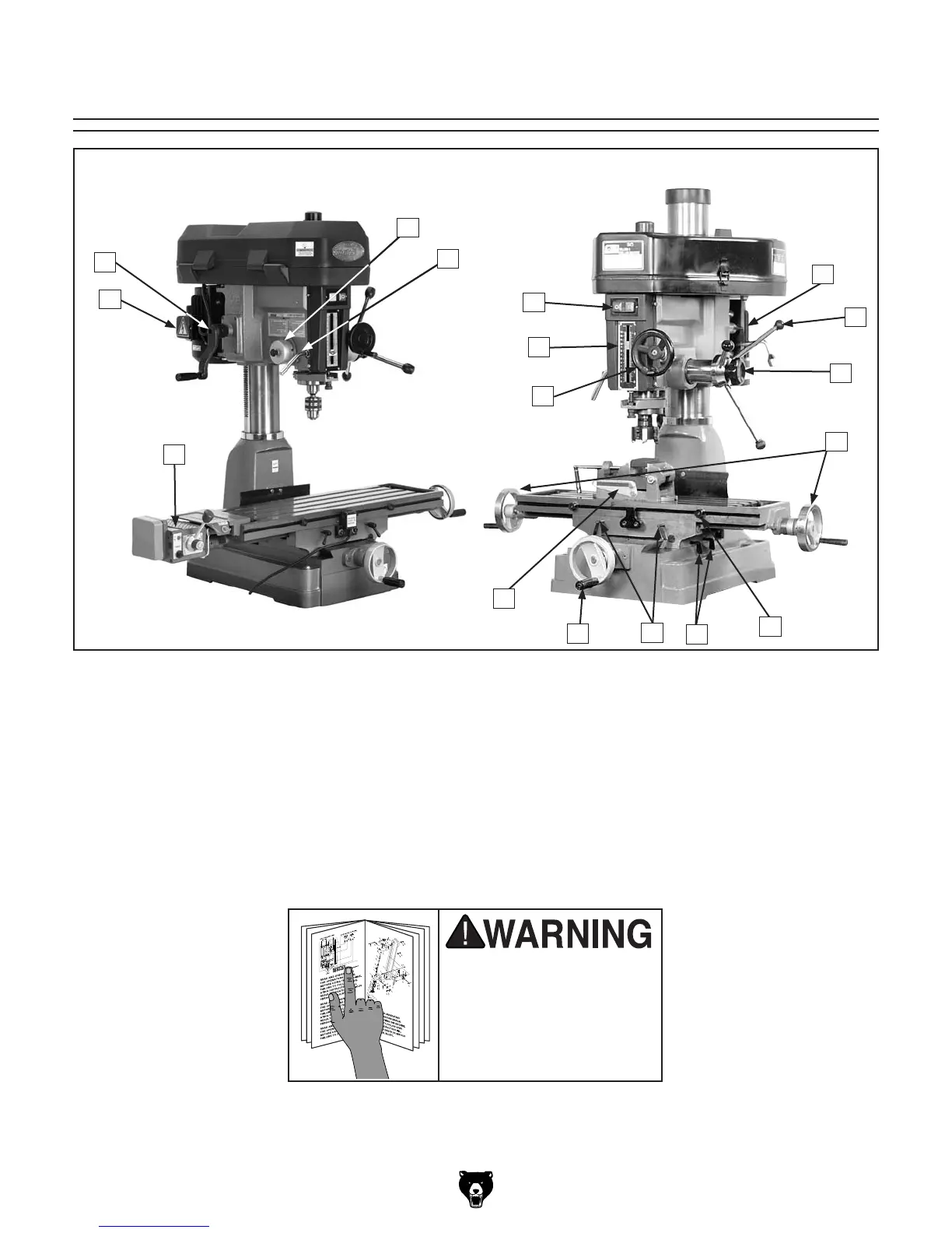
Figure 3. Identification.
Identification
A. Junction Box
B. Headstock Height Crank
C. Return Spring Assembly
D. Quill Lock
E. ON/OFF Swtich
F. Depth Stop
G. Micro-Downfeed Handwheel
H. Motor Pivot Lock
I. Downfeed Handles
A
B
E
F
G
H
I
J
L
O
K
P
N
M
J. Pinion Hub Lock Knob
K. X-Axis Handwheels
L. Longitudinal Stops
M. Y-Axis Lock Handles
N. X-Axis Lock Handles
O. Y-Axis Handwheel
P. Drilling Angle Vise
Q. Power Feed (G1007 Only)
G1006G1007
Q
C
D
 Loading...