12
Maintenance
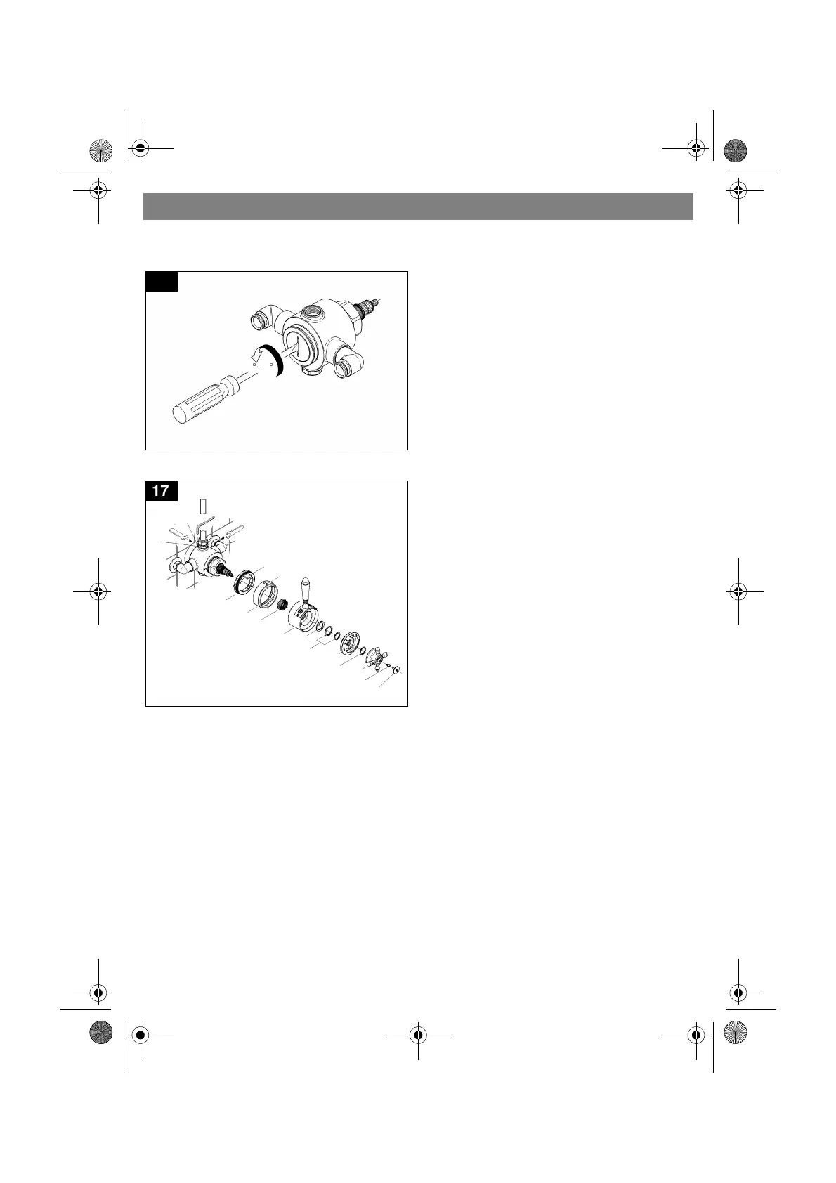
7.Unscrew seat 1/8 to 1/6 turn (45qto
60q), see Fig. [16].
8.Slide valve on the supplies, see Fig. [17]
9.Tighten set screw (D1) and compression
nuts.
10.Install shower and tighten outlet
nipple (L).
11. Push on stop ring (T) with catch (T1)
on top.
12.Reinstall cover ring (S) with mark (S1)
on top.
13.Push on adapter (R).
14.Push on shut-off lever (Q) in closed
position.
15.Reinstall washer (Q2) and fix with cir-
clips (Q1), the smaller one is to be
placed in the middle of the unit stem.
16.Push on scale ring (P) with WARM on
top and fix with clip (P1).
17.Reinstall the temperature cross
handle (O) in position hot water.
18.Fix temperature cross handle with
screw (N) and cover with cap (M).
Readjustment is necessary after every
maintenance operation on the control unit,
see chapter “Adjustment” on page 10.
II.Non-return valve, see spare parts
drawing on page 3, 4 and Fig. [12].
1.Same procedure as for control unit, see
Fig. [12], points 1, 11 and 12.
2.Unscrew elbow, see spare parts drawing
on page 3 and 4.
3.Remove threaded ring with flow
limiter (9.1) if installed.
4.Take out and replace non-return
valve (9.2).
Reassemble in reverse order.
Only genuine GROHE replacement parts
must be used.
16
45
q
-60
q
P1
17
M
N
S
T
2
.
5
m
m
2
4
m
m
R
T1
S1
Q1
L
2
4
m
m
D1
Q
O
P1
Q2
P
956212.book Seite 12 Mittwoch, 19. Dezember 2001 8:04 08