7
Installation
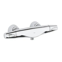
his thermostatic shower mixing valve is to
e installed with the outlet at the top for use
ith the headshower.
f there is a pressure differences between
he hot and cold water supply install
ttached flow limiters in the water
onnection elbows, see table below.
x Screw out connection elbows (A), see
Fig. [1].
x Install flow limiters (B) in accordance to
table above with threaded rings (C) by
using a 12mm socket spanner.
he thermostatic mixing valve is fixed to the
all via the backplate and connected to the
upply pipes by a pair of elbows. The elbows
re preassembled to the valve body. The
alve body is fixed to the backplate by a set
crew.
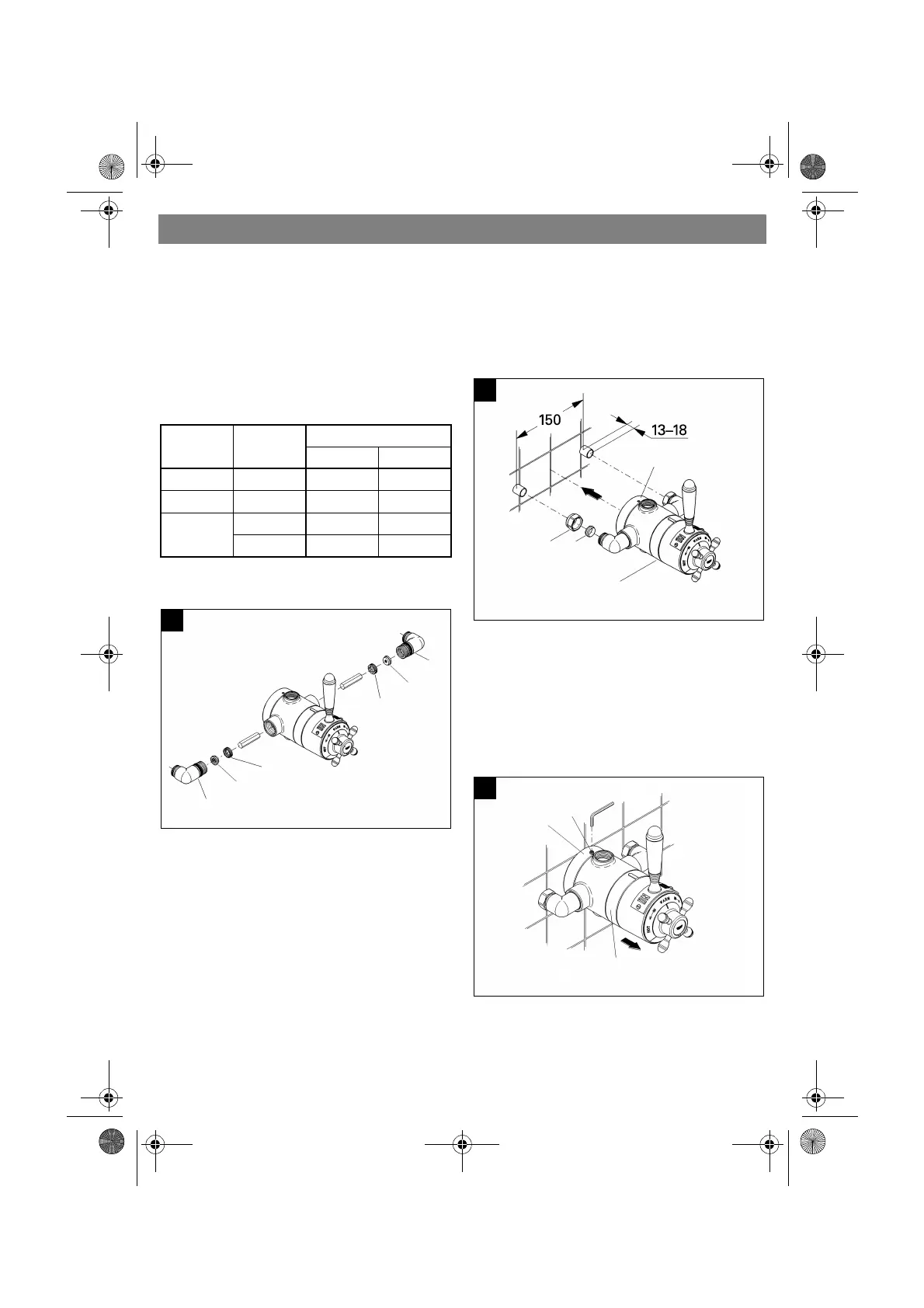
In case of exposed installation with supply
pipes from above or below rotate inlet
elbows 90q and connect to 15mm supply
pipes.
1.Loosely screw on nuts (A1) with com-
pression rings (A2), see Fig. [2].
2.Ensure that the projections of the supply
pipes, (i.e. exposed beyond the wall sur-
face) have the correct length (13 - 18mm
and distance (150mm).
3.Place the valve body (E) with the elbows
and backplate (D) to the supply pipes.
4.Loosen set screw (D1), see Fig. [3].
5.Remove valve body (E) from supply pipe
and hold backplate (D) in position.
Cold Water
Inlet
Warm Wa-
ter Inlet
Connection
Cold Warm
0.1 - 1 bar 0.1 - 1 bar without without
1 - 5 bar 1 - 5 bar 7 l (green) 5 l (yellow)
1.5 - 10 bar 0.1 - 0.5 bar 7 l (green) without
> 0.5 bar 7 l (green) 5 l (yellow)
1
B
C
1
2
m
m
A
B
C
1
2
m
m
A
2
D
E
A1
A2
3
D
E
D1
2
.
5
m
m
956212.book Seite 7 Mittwoch, 19. Dezember 2001 8:04 08