English (GB)
13
9. Systems with bypass valve between flow and
return pipes
9.1 Purpose of bypass valve
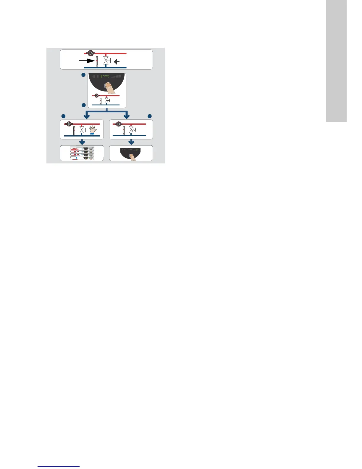
Fig. 11 Systems with bypass valve
Bypass valve
The purpose of the bypass valve is to ensure that the heat from
the boiler can be distributed when all valves in the underfloor-
heating circuits and/or thermostatic radiator valves are closed.
System elements:
• bypass valve
• flowmeter, pos. A.
The minimum flow must be present when all valves are closed.
The pump setting depends on the type of bypass valve used, i.e.
manually operated or thermostatically controlled.
9.2 Manually operated bypass valve
Follow this procedure:
1. Adjust the bypass valve with the pump in setting I (speed I).
The minimum flow (Q
min.
) for the system must always be
observed. Consult the manufacturer's instructions.
2. When the bypass valve has been adjusted, set the pump
according to section 8. Setting the pump.
9.3 Automatic bypass valve (thermostatically
controlled)
Follow this procedure:
1. Adjust the bypass valve with the pump in setting I (speed I).
The minimum flow (Q
min.
) for the system must always be
observed. Consult the manufacturer's instructions.
2. When the bypass valve has been adjusted, set the pump to
the lowest or highest constant-pressure curve.
Explanation to pump settings in relation to performance
curves, see section 11. Pump settings and pump
performance.
TM05 8150 2013