English (GB)
8
5. Dismantling and assembly
5.1 General information
If it is necessary to dismantle the pump, either because it is
choked or damaged, please follow the instructions in the following
sections.
Position numbers of parts (digits) refer to section 7. Drawings;
position numbers of tools (letters) refer to section 4. Service
tools.
Before dismantling the pump
• Disconnect the electricity supply to the motor.
• Close the isolating valves, if fitted, to avoid draining the
system.
• Remove the electric cable in accordance with local
regulations.
Before assembly
• Clean and check all parts.
• Replace defective parts by new parts.
• Order the necessary service kits.
• Gaskets and O-rings should always be replaced when the
pump is overhauled.
During assembly
• Lubricate and tighten screws and nuts to correct torque.
See section 3. Tightening torques and lubricants.
5.2 CM 1, 3, 5, cast iron
5.2.1 Dismantling
1. Remove staybolts (pos. 26).
2. Remove inlet part (pos. 6).
3. Remove gasket (pos. 139b) and chamber (pos. 4e).
4. Hold clamp (pos. 64c), and remove nut (pos. 67).
5. Remove lock washers (pos. 66) and clamp (pos. 64c).
6. Remove impeller (pos. 49).
7. Remove bearing ring (pos. 47a) and short spacing pipe
(pos. 64a).
8. Remove chamber for bearing (pos. 4a), gasket (pos. 139b),
impeller (pos. 49) and spacing pipe (pos. 64).
9. Continue the dismantling until shaft seal (pos. 105).
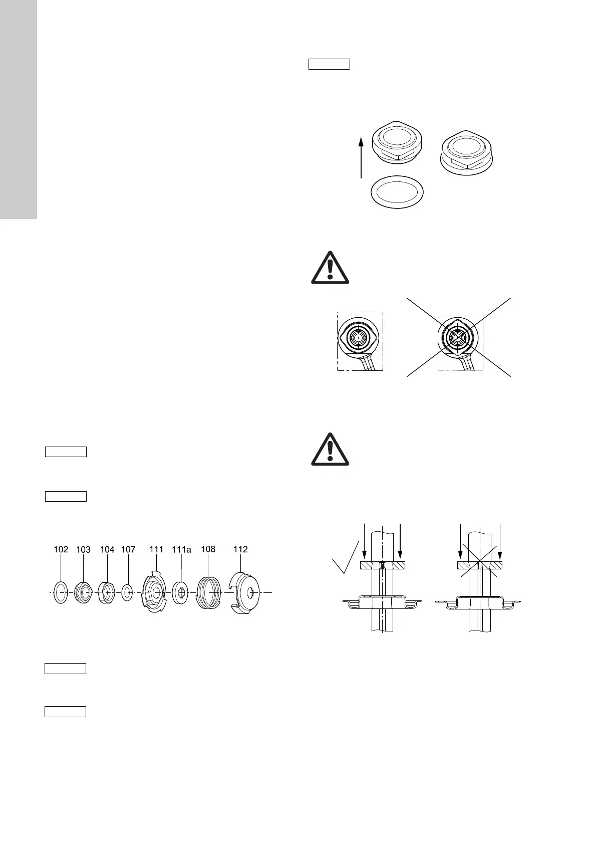
10.Remove shaft seal (pos. 105). See fig. 3.
Fig. 3 Exploded view of shaft seal
5.2.2 Assembly
1. Fit O-ring (pos. 102) on the stationary shaft seal part.
See fig. 4. For correct lubricant, see section 3. Tightening
torques and lubricants.
Fig. 4 Fitting the O-ring on the stationary shaft seal part
2. Press the stationary shaft seal part home. See fig. 5.
Fig. 5 Fitting the stationary shaft seal part (only SiC/SiC)
3. Fit the rotating shaft seal part (pos. 104) so that the seal face
touches the stationary part.
4. Fit O-ring (pos. 107) into the rotating shaft seal part
(pos. 104). For correct lubricant, see section 3. Tightening
torques and lubricants.
5. Fit retainer (pos. 111) and stop ring (pos. 111a). See fig. 6.
Fig. 6 Fitting the stop ring
Step 7 applies only to pumps with eight stages.
Step 8 applies only to pumps with eight stages.
TM04 4327 1209
Dismantling of MG 71 and MG 80,
see section 5.6.1.
Dismantling of MG 90 and MG 100,
see section 5.7.1.
It is advisable always to replace wear rings
(pos. 45) and wear ring retainers (pos. 65).
See section 5.8.
Assembly of MG 71 and MG 80, see section 5.6.2.
Assembly of MG 90 and MG 100, see section 5.7.2.
TM04 4322 1209
Warning
Do not touch the seal face.
TM04 4436 1209
Warning
Do not touch the seal face.
TM04 4325 1209
 Loading...