English (GB)
4
2. Type identification
This section shows the nameplate, the type key and the codes
that can appear in the variant code.
2.1 Nameplate
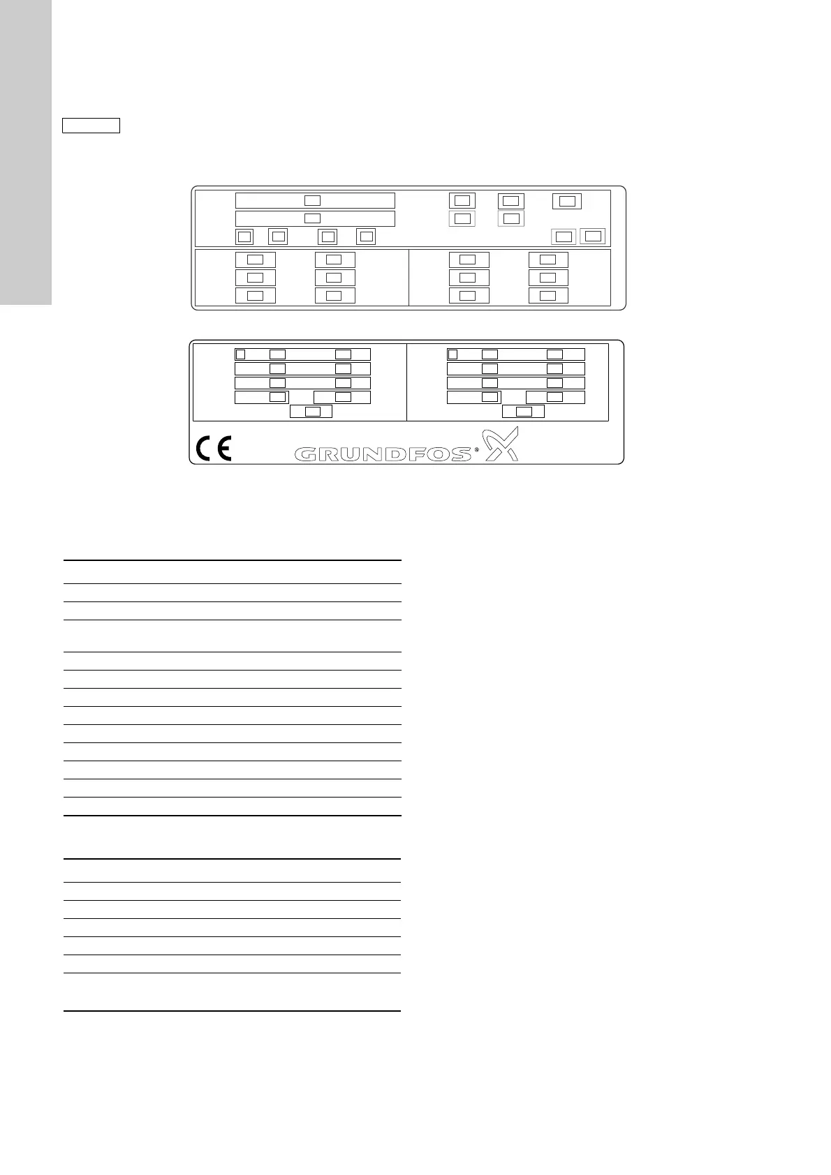
Fig. 1 Pump nameplate
Fig. 2 Motor nameplate
The pump and motor nameplates are positioned on the motor fan
cover or terminal box.
The data and information on the pump nameplate are described
in the table below.
The data and information on the motor nameplate are described
in the table below.
As codes can be combined, a code position may
contain more than one code (letter).
TM04 0355 0908
Model
IP
T
Type
P
max
T
liq,max
bar
MPa
PSI
Q
nom
H
nom
H
max
m³/h GPM
Env
m
m
PSI
PSI
Q
nom
H
nom
H
max
m³/h GPM
m
m
PSI
PSI
°C
°F
50 Hz
95120839
60 Hz
3
4
5
5
6
7
7
8
9
10 10
11 11
12 12
6
6
1
10
11
12
10
11
12
2
Amb
°C
°F
Insulation class
TM04 0356 0908
I max
~/V
/A
/A
uF / V
kW
95120836
I 1/1
P2
I max
~/V
/A
/
A
I 1/1
P2
Capacitor
HP kW HP
uF / V
Capacitor
50 Hz 60 Hz
112
3
4
5
2
3
4
5
2
3
4
5
2
3
4
5
6 6
Pos. Description
1 Pump type
2 Pump model
3
Environmental rating for enclosures based on NEMA
type designations
4 Enclosure class
5 Maximum ambient temperature [°C] / [°F]
6 Maximum system pressure [bar] / [psi] / [MPa]
7 Maximum liquid temperature [°C] / [°F]
8 Insulation class
9 Motor protection
10 Rated flow [m
3
/h] / [GPM]
11 Head at rated flow [m] / [psi]
12 Maximum head [m] / [psi]
Pos. Description
1 Number of phases
2 Voltage [V]
3 Maximum current [A]
4 Rated current [A]
5 Power output [kW] / [hp]
6
Single-phase pumps only:
Capacitor size [F] and voltage [V]
 Loading...