English (GB)
21
* Pos. 1 is next to the motor.
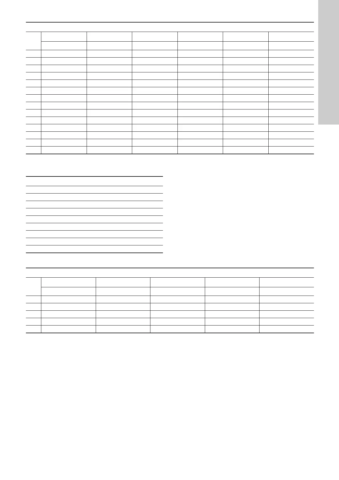
8.4 Key for CM 10, 15, 25
8.5 CM 10, 15, 25, cast iron
* Pos. 1 is next to the motor.
CM 1, 3, 5, stainless steel
Pos.
9 1011121314
Chamber Impeller Chamber Impeller Chamber Impeller Chamber Impeller Chamber Impeller Chamber Impeller
1*CFCFCFCFCFCF
2AFAFAFAFAFAF
3AFAFAFAFAFAF
4AFAFAFAFAFAF
5AFAFAFAFAFAF
6AFAFAFAFAFAF
7AFAFAFAFAFAF
8BFAFAFAFAFAF
9EFBFAFAFAFAF
10 EFBFAFAFAF
11 E EFBFBFBF
12 EFAFAF
13 EEFAF
14 EEEF
Bearings
Chamber cpl. A
Chamber with bearing cpl. B
Chamber with holes C
Impeller located in cast iron component D
Chamber without sand lift E
Chamber plate, SS pumps F
Chamber without guide vanes G
Chamber without guide vanes and sand lift H
Impeller I
CM 10, 15, 25, cast iron
Pos.
12345
Chamber Impeller Chamber Impeller Chamber Impeller Chamber Impeller Chamber Impeller
1*DIDIDIDIDI
2H EIEIEIEI
3 AIAIAI
4 AIAI
5 AI
 Loading...