English (GB)
6
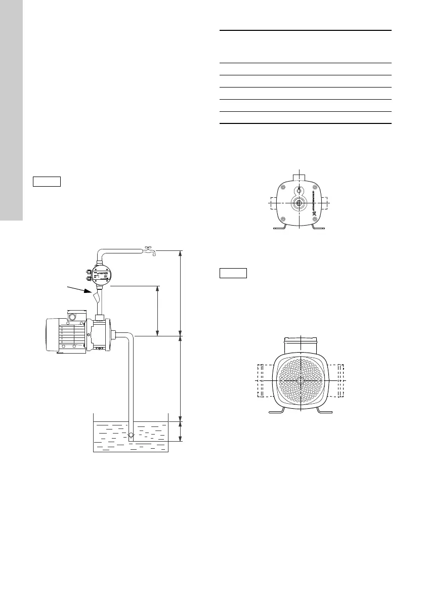
6.2.2 Pipe connection (self-priming pumps)
The pump must be installed correctly to ensure that it
can self-prime.
Take the following precautions:
See fig. 4.
• The minimum height from the centre of the
suction port to the first tapping point (H
1
) must be
observed.
If a pressure manager is installed in the system,
H
1
is the height from the centre of the pump
suction port to the pressure manager.
Minimum heights appear from the table below.
• The suction pipe must be at least 0.5 metres
below the liquid level (H
3
).
We recommend that you install a filling plug in the
discharge pipe. This facilitates liquid filling before
startup. See fig. 4, pos. A.
Fig. 4 Recommended pipework for a
self-priming pump
6.3 Alternative connection positions
The pump is available with various connection
positions on special request. See fig. 5.
Fig. 5 Alternative connection positions
6.4 Terminal box positions
The pump is available with various terminal box
positions on special request. See fig. 6.
Fig. 6 Terminal box positions
For optimum suction capability, the pump
must be located near the well or tank to
ensure that the suction pipe is as short as
possible. This will reduce the self-priming
time, especially in the case of a high
suction lift.
TM05 8415 2313
Suction lift
(H
2
)
[m]
Minimum height
(H
1
)
[m]
40.2
50.35
60.5
70.6
80.7
TM03 8709 1008
Self-priming pumps:
These pumps are only available with the
discharge port pointing upwards, i.e. in the
same direction as the filling hole.
TM04 0357 1008

 Loading...


