English (GB)
8
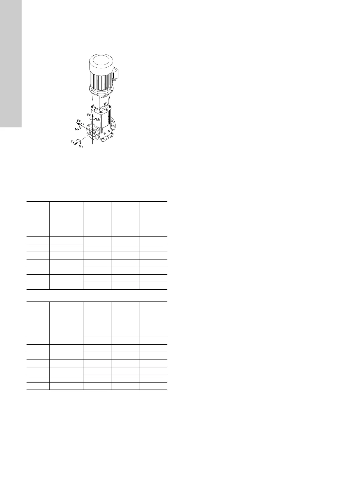
6.6 Flange forces and torques
If not all loads reach the maximum permissible value stated in the
tables below, one of these values may exceed the normal limit.
Contact Grundfos for further information.
Fig. 14 Flange forces and torques
Forces
Torques
TM04 0346 2013
Y-direction: Inlet/outlet
Z-direction: Direction of chamber stack
X-direction: 90 ° from inlet/outlet
Flange, DN
[mm]
CR, CRI, CRN
Force,
Y-direction
[N]
Force,
Z-direction
[N]
Force,
X-direction
[N]
25/32 1s to 5 900 1050 850
40 10 1100 1250 1000
50 15 and 20 1500 1550 1350
65 32 1850 2100 1700
80 45 2500 2050 2250
100 64 and 90 3350 2700 3000
125/150 120 and 150 3350 2700 3000
Flange, DN
[mm]
CR, CRI, CRN
Torque,
Y-direction
[Nm]
Torque,
Z-direction
[Nm]
Torque,
X-direction
[Nm]
25/32 1s to 5 1100 850 750
40 10 1300 1050 900
50 15 and 20 1400 1150 1000
65 32 1500 1200 1100
80 45 1150 1300 1600
100 64 and 90 1250 1450 1750
125/150 120 and 150 1250 1450 1750
 Loading...