English (GB)
5
5.5 Minimum inlet pressure
The table on page 17 states the maximum permissible inlet
pressure. However, the actual inlet pressure + maximum pump
pressure (at no flow) must always be lower than the values stated
in fig. A, page 16.
The pumps are pressure-tested at a pressure of 1.5 times the
values stated in fig. B, page 17.
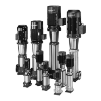
5.6 Minimum flow rate
Due to the risk of overheating, do not use the pump at flows
below the minimum flow rate.
The curves below show the minimum flow rate as a percentage of
the nominal flow rate in relation to the liquid temperature.
- - - - = air-cooled top.
Fig. 5 Minimum flow rate
5.7 Electrical data
See motor nameplate.
5.8 Frequency of starts and stops
5.9 Dimensions and weights
Dimensions: See fig. C, page 18.
Weights: See label on the packing.
5.10 Sound pressure level
See fig. D, page 19.
6. Installation
The pump must be secured to a horizontal, plane and solid
foundation by bolts through the holes in the base plate. When
installing the pump, follow the procedure below in order to avoid
damaging the pump.
TM01 2816 2302
The pump must not run against a closed
discharge valve.
Motor size
[kW]
Maximum number of starts per hour
≤ 2.2 250
3-4 100
5.5 - 11 50
18.5 - 22 40
30 90
37 50
45 80
55 50
75 50
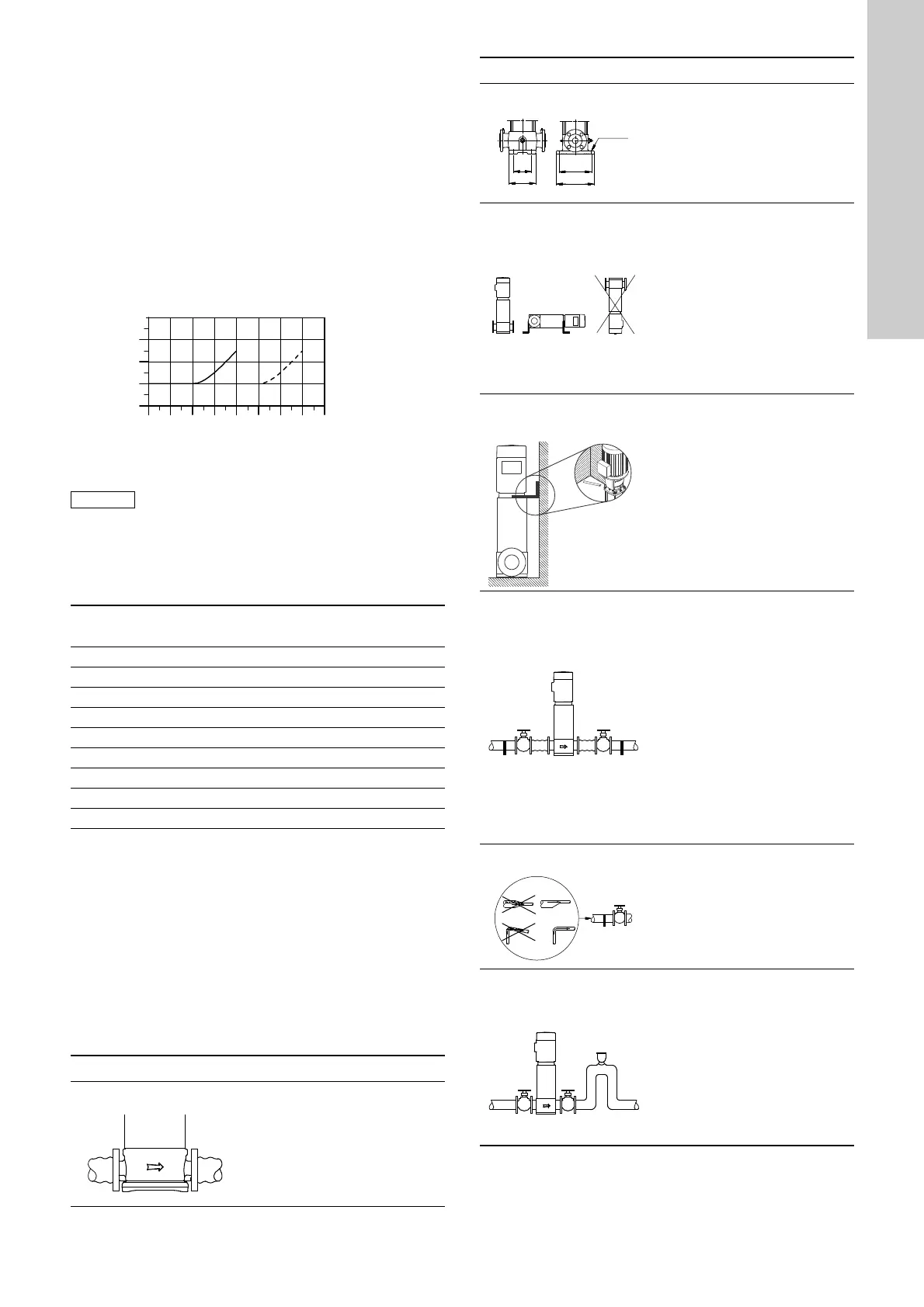
Step Action
1
TM02 0013 3800
Arrows on the pump base show
the direction of flow of liquid
through the pump.
40 60 80 100 120 140 160 180
t [°C]
0
10
20
30
Qmin
[%]
2
TM00 2256 3393
This information is stated on
page 18:
• port-to-port lengths
• dimensions of the base
• pipework connections
• diameter and position of
foundation bolts.
3
TM01 1241 4097
The pump can be installed
vertically or horizontally (CR,
CRN 120 and 150, 75 kW, only
vertically). However, the motor
must neither fall below the
horizontal plane nor be
installed upside down.
Ensure that an adequate
supply of cool air reaches the
motor cooling fan.
Motors above 4 kW must be
supported.
3a
TM05 7705 1013
(Additional support for ships’
use)
To minimise pump vibrations,
additional support brackets can
be mounted. The brackets can
be fitted from the motor or the
motor stool to the bulkhead of
the ship. Mount the bracket in
horizontal position. To minimise
further vibration, mount the
bracket at an angle of 30-40 °
to the wall.
4
TM02 0116 3800
To minimise possible noise
from the pump, we advise you
to fit expansion joints on either
side of the pump.
The foundation/installation
must be carried out as
described in section 6.1.
Fit isolating valves on either
side of the pump to avoid
draining the system if the pump
needs to be removed for
cleaning, repair or
replacement.
Always protect the pump
against backflow by means of a
non-return valve (foot valve).
5
TM02 0114 3800
Install the pipes so that air
locks do not occur, especially
on the suction side of the
pump.
6
TM02 0115 3800
Fit a vacuum valve close to the
pump if the installation has one
of these characteristics:
• The discharge pipe slopes
downwards away from the
pump.
• There is a risk of siphon
effect.
• Protection against backflow
of unclean liquids is needed.
Step Action
 Loading...