English (GB)
5
3.1.2 Installation
1. Carefully lift the motor onto the motor stool (1a) using
approved lifting equipment.
2. Install the screws (28a), washers (32a) and nuts (36a).
3. Lubricate and tighten the nuts (36a) to the specified torque.
See section 7.1 Torques.
4. Install the cylindrical pin (10) in the pump shaft (51).
5. Install the coupling halves (10a).
6. Lubricate and cross-tighten the screws (9). See sections
7.1 Torques and 7.2 Lubricants.
7. Install the coupling guards (7) and tighten the screws (7a).
See section 7.1 Torques.
3.2 Shaft seal, motor stool, pump head cover, sleeve
and chamber stack
3.2.1 Preparations
1. Remove the motor as described in section 3.1.1 Removal.
2. Close the isolating valves, if fitted, to avoid draining the pipe
system.
3. Drain the pump by loosening the vent screw (18) and
removing the plugs (25) and o-rings (38).
3.2.2 Dismantling
1. Clean the end of the shaft (51) with a cloth.
2. If the shaft seal (105) is to be reused, remove any marks or
scratches on the shaft (51) by using service tool E together
with a piece of fine emery cloth.
3. Loosen the three set screws (113) of the shaft seal (105).
Note that the set screws must be loosened no more than 1/4
turn.
4. Loosen the shaft seal by using service tool A, together with
service tools O and P.
5. Carefully lift the shaft seal (105) off the shaft (51).
Note: Shaft seals fitted on pumps with ∅28 and ∅36 pump
shafts can be fitted with new wear parts. See section
6. Renewing shaft-seal wear parts.
6. Attach approved lifting equipment to the motor stool (1a) in
order to prevent it from falling before proceeding with any
further dismantling.
7. Remove nuts (36) and washers (66a).
8. Remove the motor stool (1a).
9. Remove the pump head cover (2). It may be necessary to
loosen it from the sleeve (55) using a plastic hammer.
10. Remove the o-ring (37) from the pump head cover.
11. Pull out the outlet part (3b) from the pump head cover (2).
12. CR pumps only: Remove the four screws (60) and the
brackets (2c) from the pump head cover (2).
13. Fit service tool N on the pump sleeve (55). See fig. 1.
Fig. 1 Service tool N fitted on sleeve (55)
14. Attach approved lifting equipment to service tool N and lift the
sleeve (55) up and away from the chamber stack.
15. Fit service tool B in the top of the pump shaft.
16. Attach approved lifting equipment to service tool B and lift up
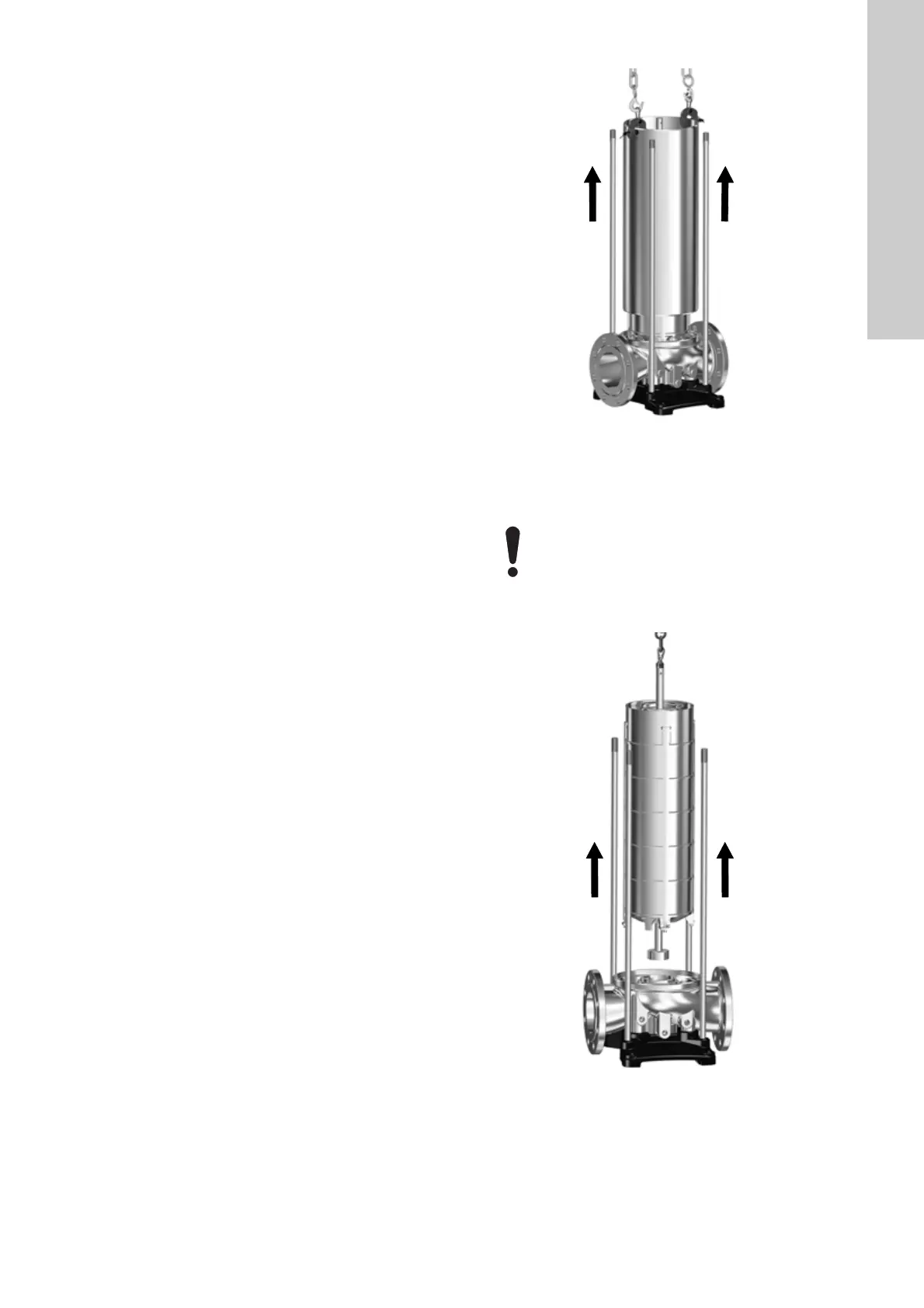
the chamber stack.
Fig. 2 Lifting the chamber stack
17. Lay down the chamber stack in a fixed position so that it
cannot move.
18. Remove the o-ring (37) from the pump base.
TM07 1740 2218
When handling the chamber stack, it is important to
pay close attention in order not to damage the
thrust-handling device (120), if fitted.
TM07 1900 2318

 Loading...


