English (GB)
8
3.3 Thrust-handling device
This section applies only for pumps fitted with a thrust-handling
device (120).
There are two ways to service the thrust-handling device:
• by completely dismantling the entire pump.
See instructions in section 3.3.1 Servicing the thrust-handling
device by dismantling the entire pump.
• by positioning the pump horizontally and accessing the
thrust-handling device from the pump base.
See instructions in section 3.3.3 Servicing the thrust-handling
device from the pump base.
3.3.1 Servicing the thrust-handling device by dismantling the
entire pump
Preparations
Removing the thrust-handling device requires that the pump has
been dismantled as described in the following sections:
• 3.1.1 Removal
• 3.2.2 Dismantling.
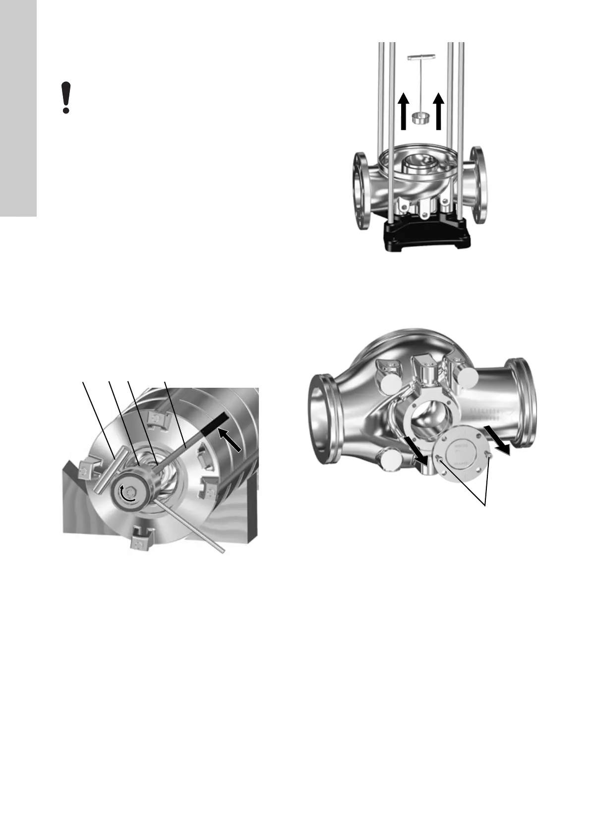
Dismantling
1. Lay down the chamber stack on a solid surface and take the
necessary precautions to prevent the chamber stack from
moving while working on it.
2. Loosen and remove the nut (120f) (Note: left-hand thread)
and washer (120e). Use service tools C, D, O and P to hold
the shaft when loosening the nut (120f).
Fig. 11 Dismantling thrust-handling device from pump shaft
3. Remove thrust-handling device parts (120a,120b, 120c,
120d). The parts come out together.
4. Remove the stationary ring (120g) together with the lifting
plate (120h) by using service tool G for pulling out the parts.
Fig. 12 Removing stationary ring (120g) and lifting plate
(120h)
5. Remove the bolts (120l) from the pump base (6).
6. Remove the flange (120k) by using two bolts (120l) as
extractors.
Fig. 13 Extracting the flange
7. To renew the thrust-handling device wear parts, see section
4. Renewing thrust-handling device wear parts.
3.3.2 Assembly
1. Install the flange (120k) in the pump base (6).
2. Fit and tighten the four screws (120l). See 7.1 Torques.
3. Fit the stationary ring (120g) together with the lifting plate
(120h) by using service tool G.
4. Fit thrust-handling device parts (120a,120b, 120c, 120d).
5. Fit the washer (120e) and nut (120f).
6. Tighten the nut (120f). See 7.1 Torques.
Note: Left-hand thread.
7. Follow the assembly instructions described in section
3.2.3 Assembly.
All parts for the thrust-handling device must be
handled very carefully in order to avoid damaging
them.
TM07 1746 2218
TM07 1745 2218TM07 1747 2218
 Loading...


