English (GB)
6
3.2.3 Assembly
1. Lubricate and install a new o-ring (37) in the pump base (6).
See section 7.2 Lubricants.
2. Carefully lift the chamber stack with approved lifting
equipment and lower it into the pump base.
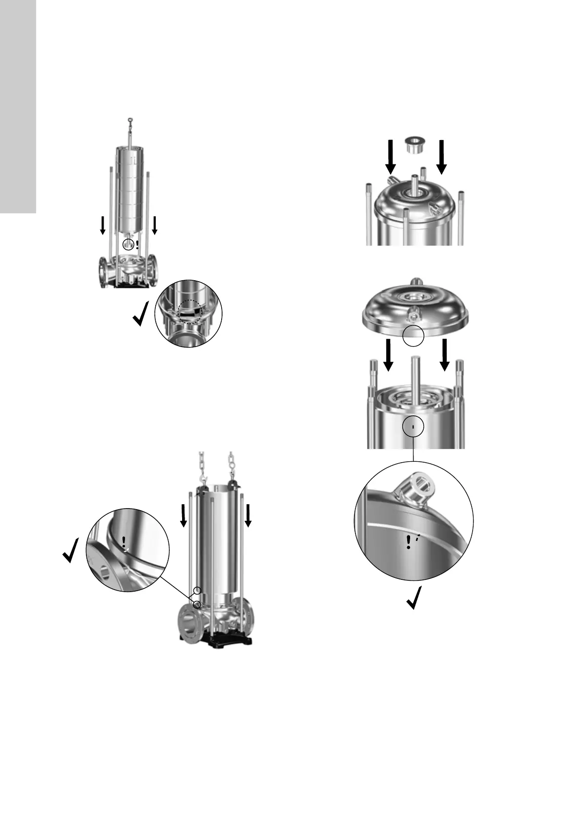
Note: Make sure to align the pump inlet part (44) with the tap
in the pump base (6). See fig. 3.
Fig. 3 Aligning inlet part (44) in pump base (6)
3. Fit service tool N on the pump sleeve (55).
4. Attach approved lifting equipment to service tool N and lift the
sleeve (55) onto the pump base (6).
Note: Make sure to align the sleeve (55) according to the
alignment marks on the sleeve (55) and on the pump base (6).
Also ensure that the sleeve (55) is pressed fully home in the
pump base (6).
Fig. 4 Aligning sleeve (55) in pump base (6)
5. Lubricate and install a new o-ring (37) in the pump head
cover. See 7.2 Lubricants.
6. CR pumps only: Install the four screws (60) and the brackets
(2c) in the pump head cover (2). See section 7.1 Torques.
7. Install the outlet part (3b) in the pump head cover (2).
8. Install the pump head cover (2) on the sleeve (55). Use
service tool J to centre the chamber stack in the pump-head
cover (2). See fig. 5.
Note: Make sure to align the pump head cover (2) according
to the alignment marks on the pump head cover (2) and on the
sleeve (55). See fig. 6.
Fig. 5 Fitting service tool J in the pump head cover (2).
Fig. 6 Aligning pump head cover (2) and sleeve (55)
9. Attach approved lifting equipment to the motor stool (1a) and
lift the motor stool (1a) onto the pump head cover (2).
10. Install washers (66a) and nuts (36).
TM07 1742 2218TM07 0849 1418
TM07 1901 2318TM07 1741 2218
 Loading...


