25
English (US)
15. Replacing the motor
For lifting instructions, see section 4.3 Lifting instructions.
If the motor is damaged due to bearing failure, burning or
electrical failure, observe the following instructions as to how to
remove the motor and how to mount the replacement motor.
15.1 Disassembly
Proceed as follows:
1. Disconnect the power supply leads from the motor. Remove
the coupling guards.
2. Use the proper metric hexagon key to loosen the four cap
screws in the coupling. Remove coupling halves completely.
On CR 1s-CR 20, the shaft pin can be left in the pump shaft.
CR, CRN 32, 45 and 64 do not have a shaft pin.
3. Use the correct size spanner to loosen and remove the four
mounting bolts joining motor and pump.
4. Lift the motor straight up until the shaft has cleared the motor
stool.
15.2 Assembly
Proceed as follows:
1. Remove key from motor shaft, if present, and discard.
2. Thoroughly clean the surfaces of the motor and pump
mounting flanges. The motor and shaft must be clean of all oil
or grease and other contaminants where the coupling
attaches. Place the motor on top of the pump.
3. Turn the terminal box to the desired position by rotating the
motor.
4. Insert the four mounting bolts, then tighten diagonally and
evenly:
– For 3/8" bolts (1/2 - 2 HP), torque = 17 ft-lb.
– For 1/2" bolts (3 - 40 HP), torque = 30 ft-lb.
– For 5/8" bolts (50 - 100 HP), torque = 59 ft-lb.
– Follow instructions for particular pump model in sections
15.2.2 CR 1s, 1, 3, and 5 to 15.2.5 CR, CRN 32, 45 and 64.
15.2.1 Torque specifications
15.2.2 CR 1s, 1, 3, and 5
1. Insert shaft pin into shaft hole.
2. Mount the coupling halves onto shaft and shaft pin.
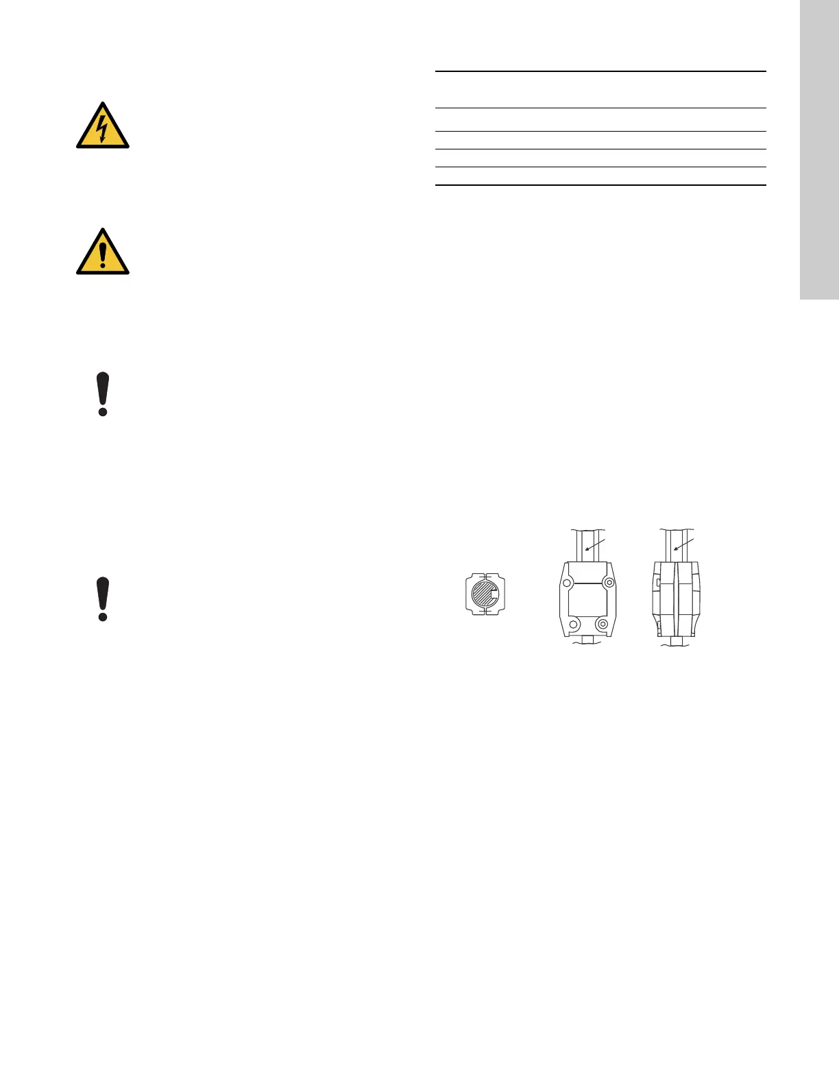
3. Fit the coupling screws and leave loose. Check that the gaps
on either side of the coupling are even and that the motor
shaft keyway is centered in the coupling half as shown in fig.
16.
4. Tighten the screws to the correct torque. See section
15.2.1 Torque specifications.
15.2.3 CR 10, 15 and 20
1. Insert shaft pin into shaft hole.
2. Insert plastic shaft seal spacer beneath shaft seal collar.
3. Mount the coupling halves onto shaft and shaft pin.
4. Fit the coupling screws and leave loose. Check that the gaps
on either side of the coupling are even and that the motor
shaft keyway is centered in the coupling half as shown in fig.
16.
5. Tighten the screws to the correct torque. See section
15.2.1 Torque specifications.
6. Remove plastic shaft seal spacer and hang it on inside of
coupling guard.
Fig. 16 Coupling adjustment all CR, CRI, CRN, CRT
DANGER
Electric shock
Death or serious personal injury
- Before starting any work on the product, make
sure that the power supply has been switched off
and that it cannot be accidentally switched on.
WARNING
Falling objects
Death or serious personal injury
- Follow the lifting instructions.
- Use lifting equipment which is approved for the
weight of the product.
- Persons must keep a safe distance to the product
during lifting operations.
- Wear personal protective equipment.
Motors used on CR pumps are specifically selected
to our rigid specifications. Replacement motors must
be of the same frame size, should be equipped with
the same or better bearings and have the same
service factor. Failure to follow these
recommendations may result in premature motor
failure.
For CR 1s, 1, 3, 5, 10, 15, and 20: Do not loosen the
three hexagon socket head cap screws securing the
shaft seal.
Torque specifications for CR, CRI, CRN 1s, 1, 3, 5, 10, 15,
and 20 CRT 2, 4, 8, and 16
Coupling screw size Minimum torque
M6 10 ft-lb
M8 23 ft-lb
M10 46 ft-lb
TM04 3919 3613
CORRECT
Keyway
Keyway
Gap between
coupling halves
CORRECT
NOT CORRECT
TOP View

 Loading...