19
English (US)
Dry running
When this function is selected, lack of inlet pressure or water
shortage can be detected. This requires the use of an accessory,
such as these:
• a Grundfos Liqtec
®
dry-running sensor
• a pressure switch installed on the suction side of a pump
• a float switch installed on the suction side of a pump.
When lack of inlet pressure or water shortage (Dry running) is
detected, the pump will be stopped. The pump cannot restart as
long as the input is activated.
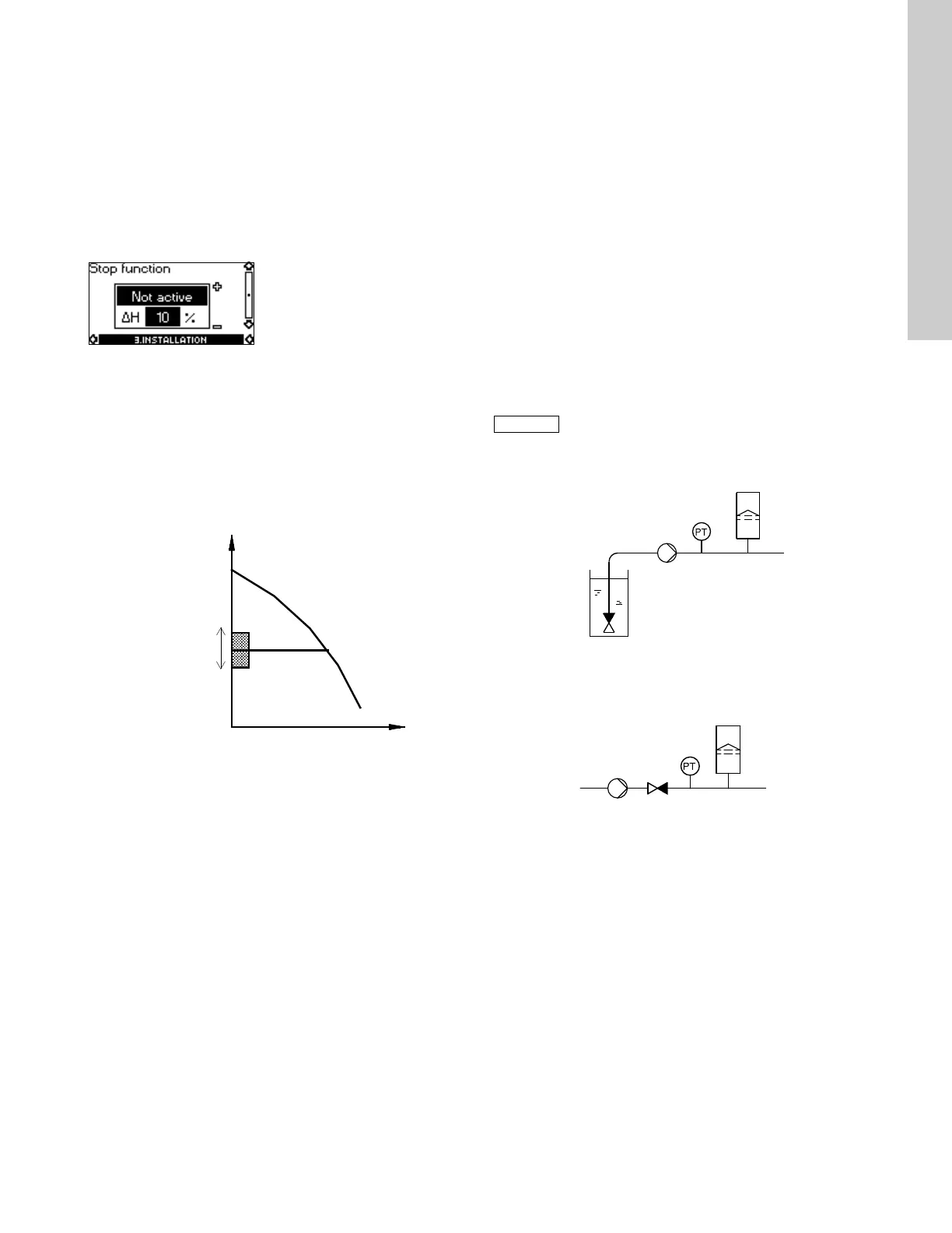
10.3.8 Stop function
The stop function can be set to these values:
•Active
• Not active.
When the stop function is active, the pump will be stopped at very
low flows. The controller will stop the pump to protect the pump
as follows:
• avoid unnecessary heating of the pumped liquid
• reduce wear of the shaft seals
• reduce noise from operation.
Fig. 27 Difference between start and stop pressures (H)
ΔH is factory-set to 10 % of actual setpoint.
ΔH can be set within the range from 5 % to 30 % of actual
setpoint.
Low flow can be detected in two different ways:
1. A built-in "low-flow detection function" which functions if the
digital input is not set up for flow switch.
2. A flow switch connected to the digital input.
1. Low-flow detection function
The pump will check the flow regularly by reducing the speed for
a short time. If there is no or only a small change in pressure, this
means that there is low flow. The speed will be increased until the
stop pressure (actual setpoint + 0.5 x ΔH) is reached and the
pump will stop. When the pressure has fallen to the start pressure
(actual setpoint - 0.5 x ΔH), the pump will restart.
When restarting, the pumps will react differently according to
pump type:
Three-phase pumps
1. If the flow is higher than the low-flow limit, the pump will return
to continuous operation at constant pressure.
2. If the flow is still lower than the low-flow limit, the pump will
continue in start/stop operation. It will continue in start/stop
operation until the flow is higher than the low-flow limit; when
the flow is higher than the low-flow limit, the pump will return
to continuous operation.
2. Flow switch
When the digital input is activated for more than 5 seconds
because there is low flow, the speed will be increased until the
stop pressure (actual setpoint + 0.5 x ΔH) is reached, and the
pump will stop. When the pressure has fallen to start pressure,
the pump will start again. If there is still no flow, the pump will
quickly reach stop pressure and stop. If there is flow, the pump
will continue operating according to the setpoint.
Operating conditions for the stop function
It is only possible to use the stop function if the system
incorporates a pressure sensor, a non-return valve and a
diaphragm tank.
Fig. 28 Position of the non-return valve and pressure sensor in
system with suction lift operation
Fig. 29 Position of the non-return valve and pressure sensor in
system with positive inlet pressure
TM00 7744 1896
Stop pressure
ΔH
Start pressure
H
Q
The non-return valve must always be installed
before the pressure sensor. See fig. 28 and
fig. 29.
TM03 8582 1907TM03 8583 1907
Pressure sensor
Diaphragm tank
Non-return
valve
Pump
Diaphragm tank
Pressure sensor
Pump Non-return valve

 Loading...