• Place the product in a flood-safe place.
• Make sure that the ambient temperature is within the limits.
• Install the product as close as possible to the connected pumps, sensors, and accessories.
• The product must be protected from direct sunlight.
• The product must be easily accessible.
• Outdoor installation: the product must be installed in a protective shed or enclosure, class IP 54.
• Indoor installation:The product must be installed in a well-ventilated room to ensure cooling of its components.
2.2 Mechanical installation
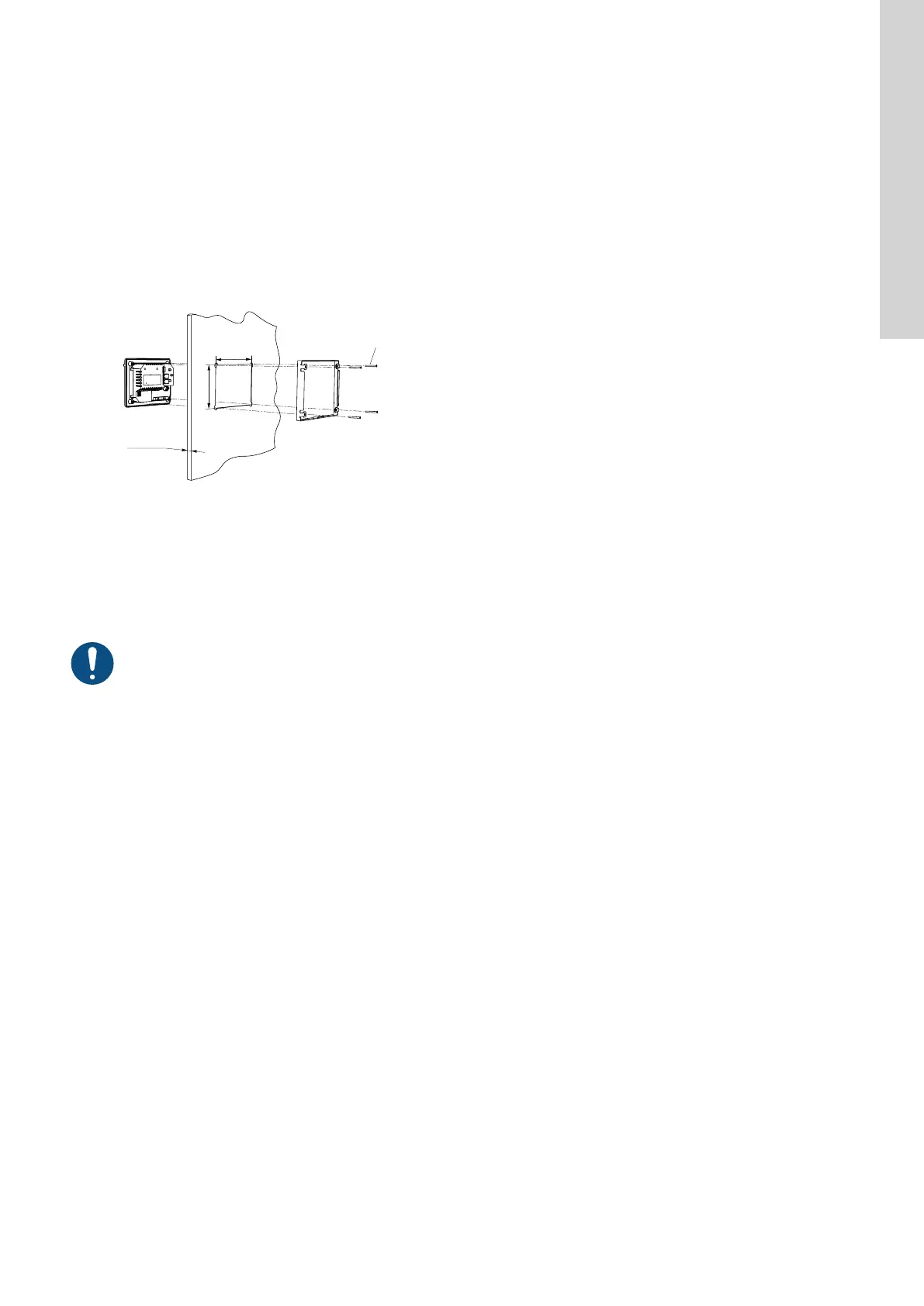
2.2.1 Mounting the control unit
1. Fasten the control unit with the four screws (1), M4 x 12, supplied with the unit. Torque value: 0.5 Nm.
1
160.5 (6.3")
110.5 (4.35")
Min. 1 (0.04")
Max. 5 (0.2")
TM072345
Fig. Mounting the control unit
Related information
8.2 Replacing the control unit
2.2.2 Installing a communication interface module
You can fit a communication interface module (CIM) in the control unit to enable communication with external systems. The module is optional
and is not delivered with the product. See the installation and operating instruction for the module regarding electrical connections.
Use an antistatic service kit when handling electronic components. This prevents static electricity from damaging the components.
7
English (GB)