12
4. Position of LEDs
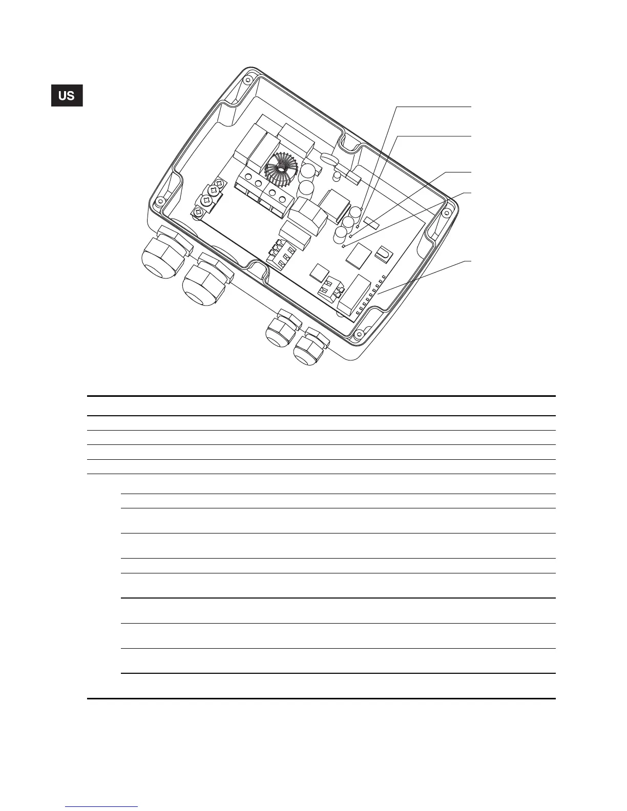
Fig. 14 Position of the LEDs inside the CU 301
TM01 8537 1606
1
2
3
4
5
Pos. Indication Description
1 +24 V overload Permanent red light when the internal 24 VDC supply is overloaded.
2 +24 V Permanent green light when the internal 24 VDC supply is OK.
3 +10 V Permanent green light when the internal 10 VDC supply is OK.
4 +5 V Permanent green light when the internal 5 VDC supply is OK.
5
9 indicator lights:
Control indicator Flashing green light when the pump control is working correctly.
Min. speed
Permanent yellow light when the pump is running at minimum speed,
3,000 rpm.
Max. speed
Permanent yellow light when the pump is running at maximum speed,
10,700 rpm.
Sensor defective *) Permanent red light when the sensor signal is out of signal range.
Overload *)
Permanent red light when the motor load exceeds the stop limit,
see section 8. Technical data.
Overtemperature *)
Permanent red light when the motor temperature exceeds the stop limit,
see section 8. Technical data.
Speed reduction *)
Permanent red light when the pump speed is reduced,
see section 8. Technical data.
Voltage alarm *)
Permanent red light when the supply voltage is out of range, see section
8. Technical data.
No contact to pump *)
Permanent red light when communication between the CU 301 and the
pump is impossible.
*) Press the On/Off button to reset the alarm indication.