8
1.5 Positioning the pressure sensor
Pressure losses often cause inconvenience to the
user. The CU 301 keeps the pressure constant in the
place where the pressure sensor is positioned, see
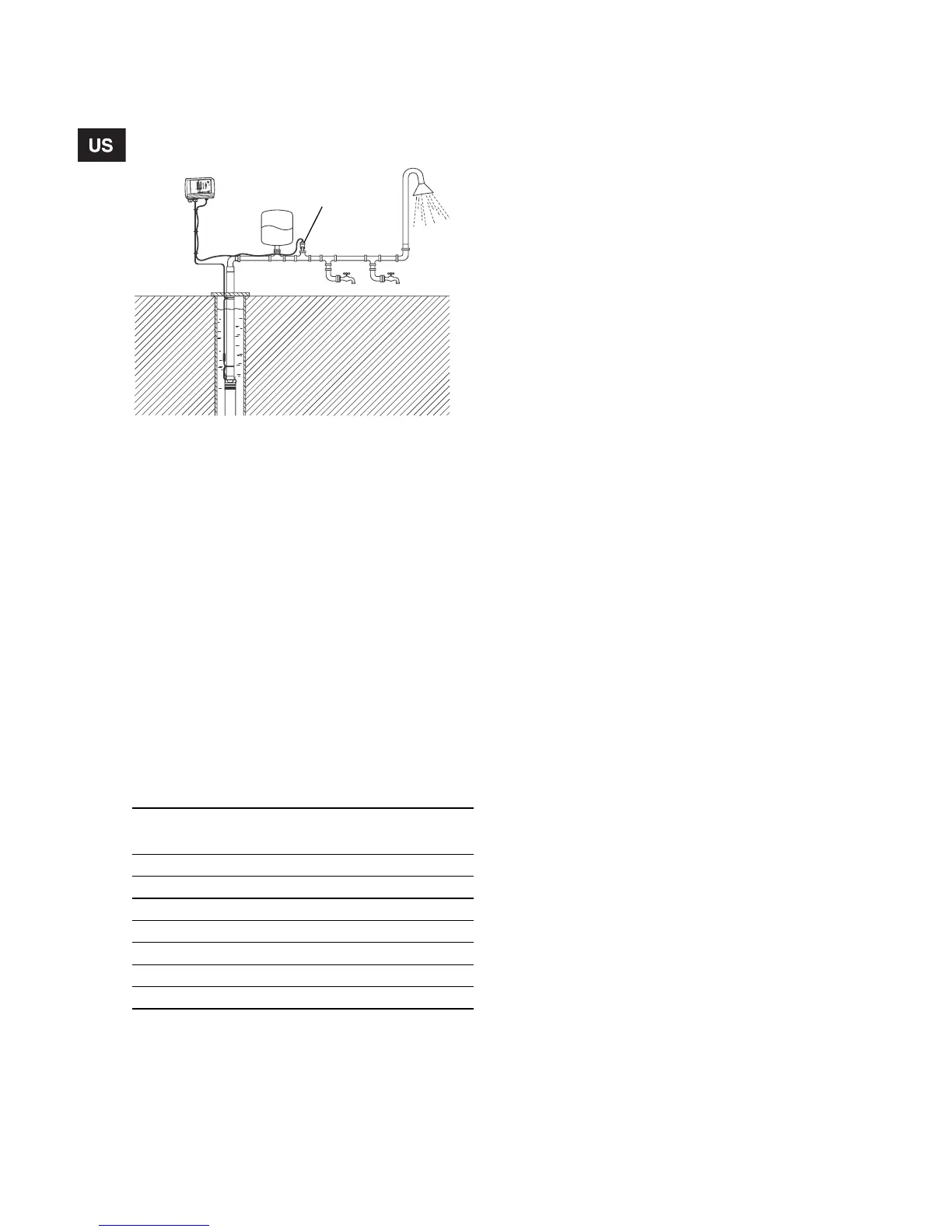
fig. 7.
Fig. 7 Pressure sensor position
In fig. 7, tap 1 is placed close to the pressure sensor.
Therefore, the pressure will be kept nearly constant
at tap 1, as the friction loss is small. At the shower
and tap 2, the friction loss is greater. This, of course,
depends on the piping.
Therefore, it is recommended that the pressure sen-
sor be positioned as close to the places of consump-
tion as possible.
1.6 Precharge pressure setting
The CU 301 is designed to work with a 2 gal. dia-
phragm tank.
The precharge pressure of the diaphragm tank must
be set to 70% of the pressure setting in order to use
the tank to the limit of its capacity. This is of course
especially important when the tank volume is limited
to 2 gal.
Use the values in the following table.
Prechange pressure is measured with 0 psi in the
pipeline:
Note: If the precharge pressure is higher than the
pressure setting, the system will have difficulty con-
troling the pressure.
If the user wants to adjust the pressure without
changing the precharge pressure of the diaphragm
tank, the precharge pressure must be equal to the
lowest pressure setting used. This means that the
control will work but that the pressure fluctuations
might increase.
1.7 Pressure relief valve
In order to provide protection against the possibility
of an overpressurization, a pressure relieve valve
should be installed down stream of the well head.
The setpoint of the pressure relief valve should be at
least 30 psi above the pressure setting, see section
2.3.
If a relief valve is installed, it is recommended that its
discharge be plumbed into an appropriate drainage
point.
TM01 7862 4999
Setting
[psi]
Precharge pressure
[psi]
40 28
50 35
60 42
70 49
80 56
90 63
100 70
Tap 1
Tap 2
Pressure sensor