26
Input for external sensor
• Voltage signal:
0-10 VDC/2-10 VDC, R
i
= 11 kΩ.
Tolerance: ±3% at maximum voltage signal.
#22 ga. Screened cable is recommended.
Maximum cable length: 1640 ft (500 m).
• Current signal:
DC 0-20 mA/4-20 mA, R
i
= 500 Ω.
Tolerance: ±3% at maximum current signal.
#22 ga. Screened cable is recommended.
Maximum cable length: 1640 ft (500 m).
Factory settings
*) 200-240 V motors: Operation is guaranteed up to 280 VAC.
100-115 V motors: Operation is guaranteed up to 150 VAC.
In order to avoid unnecessary stops, the overvoltage stop limit is as stated.
**) The 550 W dry-running limit only applies to 10 SQE 160 and 10 SQE 160 N pumps.
Accuracy of R100 readings
Operation
Sensor
The sensor signal accuracy depends on the sensor
type. See the sensor specifications in question.
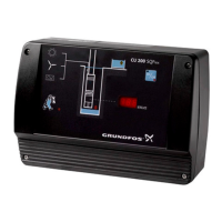
8.1 Electrical connection
The electrical connection should be carried out by an
authorized electrician.
IMPORTANT
The On/Off button on the CU 301 must not be
used as a safety switch when installing and ser-
vicing the pump.
Mains disconnector must be provided by the
installer.
"Raintight or wet location hubs that comply with
the requirements in the standard for Fittings for
Conduit and Outlet Boxes, UL514B, are to be
used. Suitable devices for CU 301 are rated with
enclosure type 3, 3R, 3S, 4, 4X, 6 or 6P".
The supply voltage and frequency are marked on the
nameplate. Make sure that the CU 301 is suitable for
the electricity supply on which it will be used.
If the CU 301 is connected to an electric installation
where a Ground Fault Circuit Interrupter (GFCI) is
used as an additional protection, this device must
trip out when earth fault currents with DC content
(pulsating DC) occur.
The CU 301 has two terminal blocks:
• Terminals 1 to 4.
• Terminals 5 to 7.
Furthermore, the CU 301 is equipped with two screw
terminals for the protective earth leads (PE).
Always use copper conductors approved for 60/75°C
(140/167°F).
Alarm
200-240 V motors 100-115 V motors
SQ/SQE/
SQE-NE
0.5 hp
SQ/SQE/
SQE-NE
0.75 hp
SQ/SQE/
SQE-NE
1.0 hp
SQ/SQE/
SQE-NE
1.5 hp
All models
Sensor defective 4-20 mA (the value is stored in the CU 301)
Overload 5.2 A 8.4 A 11.2 A 12 A 11 A
Overtemperature
Stop limit:
167°F (75°C)
Stop limit:
180°F (82°C)
Stop limit:
198°F (92°C)
Stop limit:
203°F (95°C)
Stop limit:
185°F (85°C)
Restart:
145°F (63°C)
Restart:
162°F (72°C)
Restart:
180°F (82°C)
Restart:
185°F (85°C)
Restart:
167°F (75°C)
Speed reduction In connection with undervoltage or overload
Overvoltage *) 315 VAC 315 VAC 315 VAC 315 VAC 180 VAC
Undervoltage
Speed reduction when the supply voltage is below:
198 V 198 V 207 V 207 V 90 V
Stop limit:
150 V
Stop limit:
150 V
Stop limit:
150 V
Stop limit:
150 V
Stop limit:
75 V
Dry running 300 W/550 W** 680 W 800 W 900 W 300 W/550 W**
Display Accuracy
5.2.2 Actual pressure ±1.4 psi
5.2.3 Speed ±1%
5.2.4 Temperature ±5%
5.2.5 Power input and power
consumption
±5%
Never make any connections on the
CU 301 terminal block unless the electric-
ity supply has been switched off. The
CU 301 must be connected in accordance
with the local rules and regulations.