19
Functions
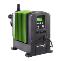
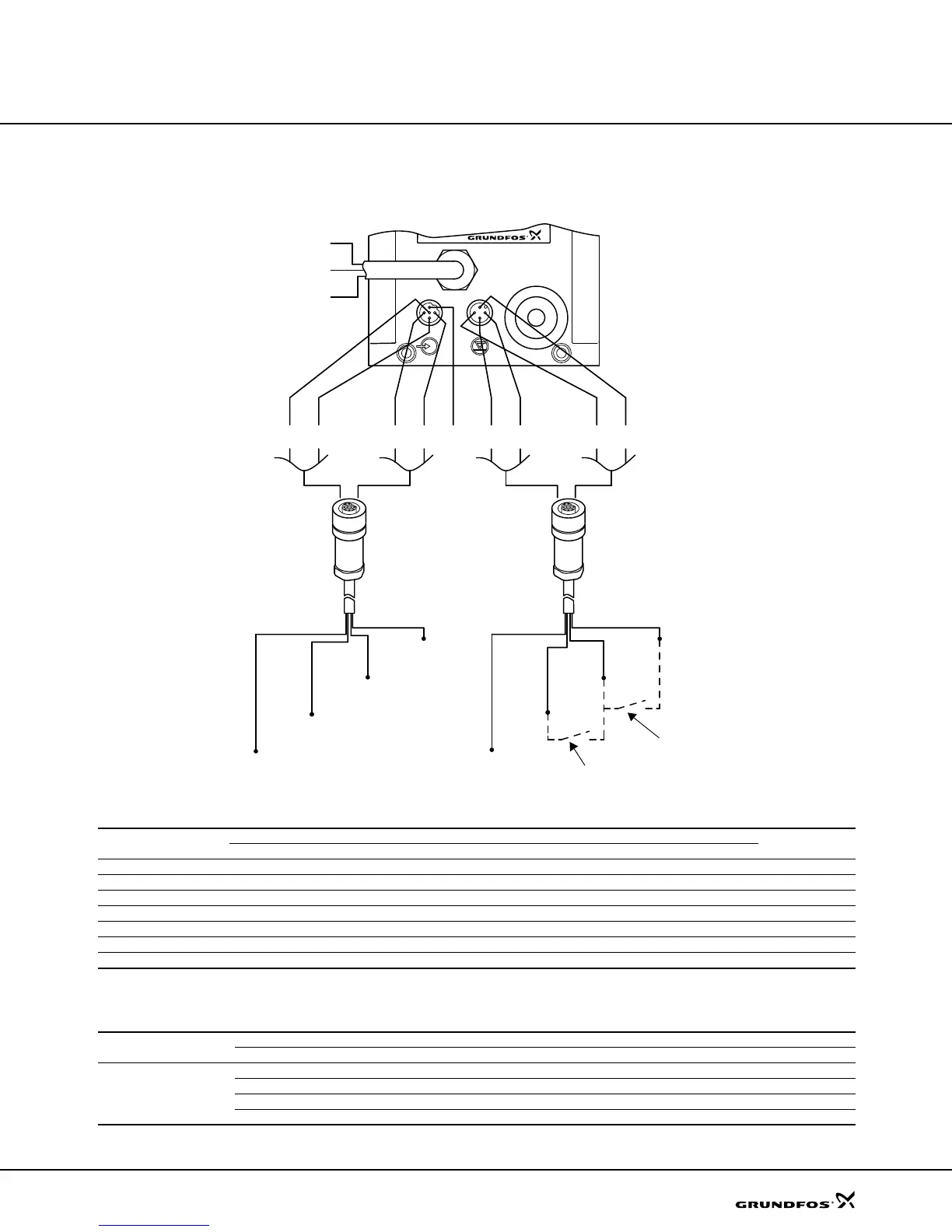
DME and DMS
Wiring diagram, DME 2 to 48 and DMS-A (AR)
See pages 30 and 32 for input/output data.
Control input
Level input
TM01 8422 5001
2
3
1
4
1
3
4
5
1
3
4
5
3
1
4
2
2
The level switch contacts (normally open) must be closed at low level/empty tank.
Low level
Empty tank
Level cable
Product no.:
2 m cable: 96440450
5 m cable: 96440451
Control cable
Product no.:
2 m cable: 96440447
5 m cable: 96440448
"NO" black
"NC" blue
"COM" brown
Number/color
Function
Plug
Description
1/brown 2/white 3/blue 4/black 5/grey
Manual 2 2
Pulse 1 1
Pulse + external on/off 1 1 + 2 2
Analog – + mA signal
Analog + external on/off 2 2 – + mA signal
Timer + external on/off 2 2
Batch 1 1
1 = Contact for pulse signal / 2 = Contact for external on/off
Pumps in analog mode cannot be connected in series.
Number/color
Plug
1/brown 2/white 3/blue 4/black
Function
Low level Low level
Empty tank Empty tank
Low level Empty tank Low level + empty tank
Dosing monitoring Dosing monitoring
Dm123.book Page 19 Tuesday, February 8, 2005 8:24 AM
 Loading...