20
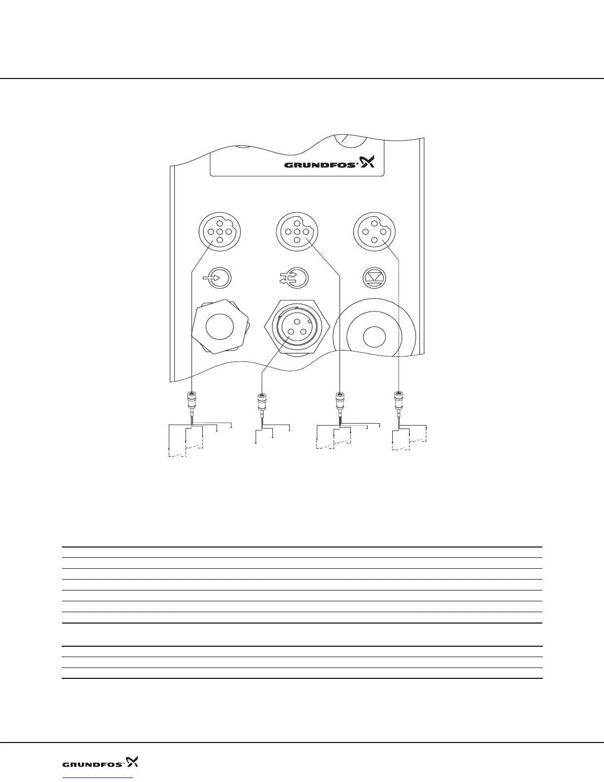
Wiring diagram, DME (60 to 940)
Cable 1: Analog, pulse and leakage input
Cable 2: Output for alarm relay
TM0 27069 2503
2
1
3
4
5
3
1
4
2
3
1
2
3
1
5
2
5
2
2
3
1
1
3
4
5
2
1
3
4
2
1
3
4
Analog/Pulse/Leakage cable
Product no.:
2 m cable: 96440447
5 m cable: 96440448
Relay cable
Product no.:
2 m cable: 96534214
5 m cable: 96534215
Stop dosing cable
Product no.:
2 m cable: 96527109
5 m cable: 96527111
Level cable
Product no.:
2 m cable: 96440450
5 m cable: 96440451
Number/color 1/brown 2/white 3/blue 4/black 5/grey
Function
Analog input 4-20 mA (-) 4-20 mA input (+) 4-20 mA input
Pulse potential-free potential-free
Pulse 5 V Gnd
Leakage potential-free potential-free
Leakage 5 V Gnd
Number/color 1/brown 2/white 3/blue
Function
Alarm relay output Common Normally open Normally closed
Functions
DME and DMS
Dm123.book Page 20 Tuesday, February 8, 2005 8:24 AM
 Loading...