5
General data
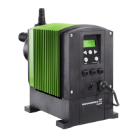
DME and DMS
Type key Codes
Example DME 2 - 18 - A - PP / E / C - F - 2 1 RR B
Type
range
Maximum capacity
[l/h]
Maximum pressure
[bar]
Control variant
Dosing head material
Gasket material
Valve ball material
Control panel position
Supply voltage
Valves
Connection suction/
discharge
Power plug type
Example A - PP / E / C - 2 - 1 R R B
Control variant
A
AG A + Genibus
AR A + alarm relay
AP A + Profibus
BBasic
DOnly on/off
Dosing head material
PP Polypropylene
PV PVDF
SS Stainless steel
Gasket material
EEPDM
VFKM
Valve ball material
C Ceramic
SS 316 SS
GGlass
Y Hastelloy C
Control panel position
F Front-fitted
S Side-fitted
X No control panel
Supply voltage
1 1 x 230 V, 50 Hz
2 1 x 120 V, 60 Hz
3 1 x 100-240 V, 50-60 Hz
6 1 x 110 V, 50 Hz
8 1 x 100 V, 50/60 Hz
9 1 x 200 V, 50/60 Hz
Valves
1 Standard valve
2 Spring-loaded valve
Connection suction/discharge
1
Tubing 6/9 mm
Tubing 4/6 mm
supplied with the pump
2
Tubing 6/9 mm
Tubing 6/12 + 9/12 mm
supplied with the pump
3 Tubing 4/6 mm
4 Tubing 6/9 mm
5 Tubing 6/12 mm
6 Tubing 9/12 mm
T Tubing 0.17"/0.25"
R Tubing 0.25"/0.375"
S Tubing 0.375"/0.5"
A Threaded Rp 1/4
B Threaded Rp 3/8
V Threaded NPT 1/4"
Y Threaded NPT 3/8"
E Cementing d.10 mm
F Cementing d.12 mm
Q Tubing 19/27 + 25/34
W Tubing 32/41 + 38/48
A1 Threaded Rp 3/4"
A2 Threaded Rp 1 1/4"
A3 Threaded NPT 3/4”
A4 Threaded NPT 1 1/4”
Power plug
F EU (Schuko)
B USA, Canada (120 V)
GUK
I Australia
E Switzerland
J Japan
Dm123.book Page 5 Tuesday, February 8, 2005 8:24 AM
 Loading...