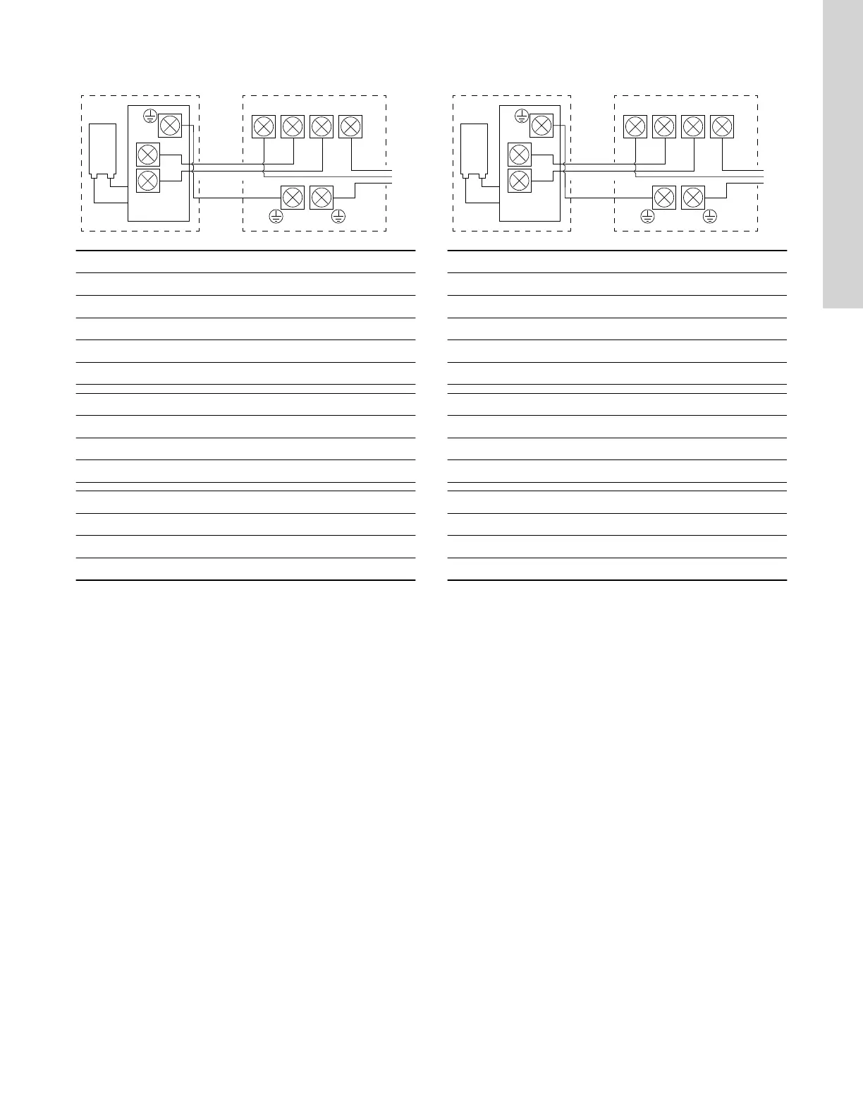
4.3.2.6 Wiring diagram, pressure switch to 115 V residential
hard wiring
TM074151
Pos. Description
PS Pressure switch
1 Residential hard wiring (in)
2 To motor (out)
3 Motor
4 Capacitor
From residential hard wiring to pressure switch
G1 Bare copper (ground)
L1 Black (live)
L2 White (neutral)
From pressure switch to motor
G2 Yellow (ground)
M1 Brown (live)
M2 Blue (neutral)
Related information
4.3.2.3 Connecting to residential hard wiring, 115 or 230 V
4.3.2.7 Wiring diagram, pressure switch to 230 V residential
hard wiring
TM074151
Pos. Description
PS Pressure switch
1 Residential hard wiring (in)
2 To motor (out)
3 Motor
4 Capacitor
From residential hard wiring to pressure switch
G1 Bare copper (ground)
L1 Black (live)
L2 Red (live)
From pressure switch to motor
G2 Yellow (ground)
M1 Brown (live)
M2 Blue (neutral)
Related information
4.3.2.3 Connecting to residential hard wiring, 115 or 230 V
13
English (US)

 Loading...