4. Connect the power cables and pump cables according to the
relevant electrical diagram, including the cables from the motor
temperature and moisture sensor, if any. Tighten the terminal
screws to the correct torque as indicated in the table below.
Note that all wires must be secured inside the cabinet
using cable ties. To ensure correct IP protection level,
all cable glands must be mounted and plugged even
if they are not in use.
Remember to remove the jumper from the PTC
terminal if you are connecting cables from the
temperature and/or moisture sensor to the PTC
terminal.
Route the wires through the left side of the cable tray.
Terminal block Torque [lb-ft (Nm)]
Pump contactor 0.89 - 1.1 (1.2 - 1.5)
Power supply 0.89 - 1.1 (1.2 - 1.5)
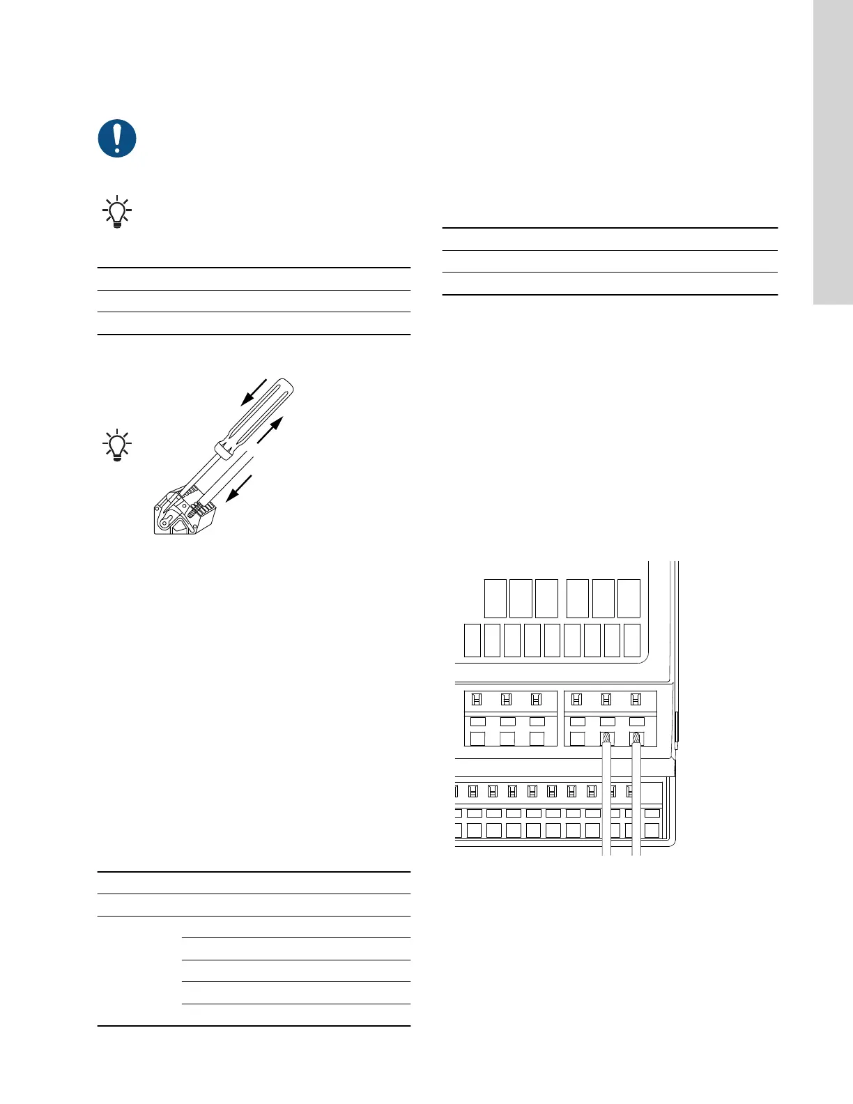
Connecting a wire to a terminal with spring clamps
TM070570
Related information
6.16.1 Thermal protection
8.2 Code 2 (Power phase missing)
8.4 Code 9 (Power phase sequence wrong)
2.3.6
Connecting a level sensor
You can either connect an analog level sensor, such as a pressure
sensor, or a digital level sensor, such as a float switch.
1. Route the wires through one of the cable glands and the cable
tray.
2. Depending on the type of cable, take one of the following
actions:
• For low-voltage cables, route the wires through the right side
of the cable tray.
• For low-voltage cables that in the event of a short circuit can
obtain high-voltage potential, route the wires through the left
side of the cable tray.
3. Depending on the type and function of the sensor, connect the
wires to the following terminals:
Sensor type
Sensor function Terminals
Analog All levels ADI - GND - 24 V
Digital
Dry-running level DI1 - GND
Stop level DI2 - GND
Start level, pump 1 DI3 - GND
Start level, pump 2 DI4 - GND
High level ADI - GND
1
DI4 is not configured when S-2 designation is selected.
Related information
3.6 Configuring the input and output terminals using Grundfos GO
Remote
2.3.7 Connecting an alarm device
You can connect an alarm device, such as a buzzer or a lamp, to
the output relays Alarm 1 and Alarm 2. The control unit triggers the
alarm device when it detects an alarm or a warning. You can
change the behavior of the outputs with Grundfos GO Remote
under Relay output 1 and Relay output 2.
Default settings of the terminal blocks
Terminal block Default function
Alarm 1 All alarms
Alarm 2 High level
1. Route the wires through one of the cable glands and the cable
tray.
2. Depending on the type of wire, perform one of the following
actions:
• For low-voltage cables, route the wires through the right side
of the cable tray.
• For low-voltage cables that in the event of a short circuit can
obtain high-voltage potential, route the wires through the left
side of the cable tray.
3. Depending on the type of alarm device, connect the wires to
the relevant terminals. Note that all wires must be secured
inside the cabinet using cable ties.
• NO (Normally Open) and C (Common)
• NC (Normally Closed) and C (Common).
4. Tie the wires with cable ties.
DI 4
GND
GND
GND
DI 3
DI 2
GND
ADI
24 V
EXT
Max. 2A Max. 2A
REL 4C
REL 3C
REL 4O
REL 3O
REL 3
REL 4
TM071997
9
English (US)
 Loading...