17
6. System for full-control operation
Description (see also page 29 or 30):
The pumps are controlled by the liquid level in the pit.
• The float switch, pos. 3, starts the first pump.
• The float switch, pos. 4, starts the next pump.
• The float switch, pos. 2, stops the last pump but one and the
float switch, pos. 1, stops the last pump. It is possible to set a
"stop delay" which delays the stop of the pumps.
• The pumps operate alternately.
6.1 Electrical connection
Full-control operation, pages 29 and 30.
Fig. D2 on page 29.
The figures show all electrical connections required to connect
the LCD 108 for direct-on-line starting, full-control operation.
Fig. D2 on page 30.
The figure shows all electrical connections required to connect
the LCD 108 for star-delta starting, full-control operation.
The operating voltage and frequency are marked on the controller
nameplate. Make sure that the controller is suitable for the
electricity supply on which it will be used.
All cables/wires must be fitted through the Pg cable entries and
gaskets (IP 65).
Maximum back-up fuse is stated on the controller nameplate.
If required according to local regulations, an external mains
switch must be installed.
Note: If the PTC resistance/thermal switch of the motor is
connected, the factory-fitted short-circuit jumper must be
removed (terminals T11-T21, T12-T22). For correct installation of
PTC resistor/thermal switch, see the installation and operating
instructions of the pump
Single-phase motors must be connected to an external operating
capacitor and in certain cases also to a starting capacitor. Further
details can be found in the installation and operating instructions
for the pump in question.
Note: Float switches of the same type as Grundfos product
number 96003332 or 96003695, i.e. float switches with
gold-plated contacts suitable for low voltages and currents
(40 V/100 mA), must be used. All EEx-approved float switches
are also suitable.
The float switches must be connected as NO contacts, i.e. brown
and black leads, when float switches, Grundfos product number
96003332 or 96003695, are used.
Key to the symbols in fig. D1 on page 30 and fig. D2 on
page 30:
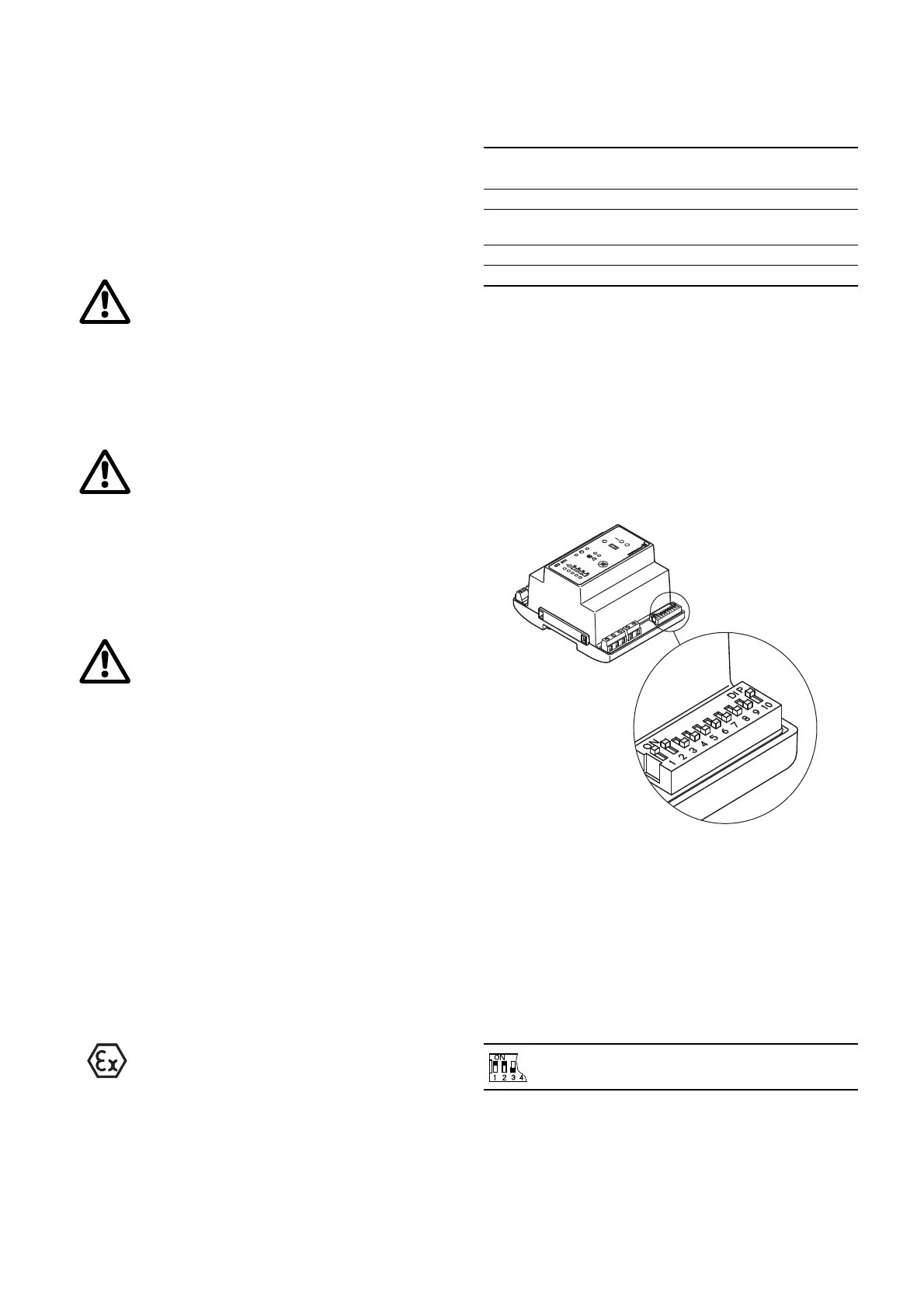
6.2 Setting
Full-control operation, pages 29 and 30.
The module CU 212 has a 10-pole DIP switch in the bottom right
corner, see fig. 11.
Note: The controller must be off circuit to ensure the correct
configuration during start-up after change of the DIP switch
setting.
The DIP switch setting offers the following possibilities:
• selection of starting delay and automatic test run (switch 4),
• setting of stop delay (switches 5, 6 and 7),
• selection of automatic alarm resetting (switch 9),
• selection of automatic restarting (switch 10).
Fig. 11
Set the DIP switch as shown in fig. 11.
Each individual switch (1 to 10) of the DIP switch can be set to
position OFF or ON.
Note: The DIP switch must not be set to other switch
combinations than those described in this section.
Set the switches 1 to 10 as follows:
• Switches 1, 2 and 3, application type:
When the DIP switch setting is changed, the controller must
be switched off for at least 1 minute!
Before starting any work on pumps used to pump
liquids which could be constituted as being
hazardous to health, thorough cleaning/venting of
pumps, pits, etc. must be carried out according to
local regulations.
Before making any connections in the LCD 108 or
work on pumps, pits, etc., it must be ensured that the
electricity supply has been switched off and that it
cannot be accidentally switched on.
Before starting work on the system, switch off the
supply voltage and lock the mains switch in
position 0.
Any external voltage connected to the system must
be switched off before work is started.
The LCD 108 must be connected in accordance with
the rules and standards in force for the application in
question.
Float switches placed in an explosion hazard area
must be connected via an EEx barrier, e.g. Grundfos
number 96440300.
The EEx barrier must not be installed in the explosion
hazard area.
Equipment used in explosion hazard areas must in
each individual case have been approved for this
particular application. Furthermore, the cables into
the explosion hazard area must be laid in accordance
with local regulations.
Pos. Description
Terminal
number
1 Float switch for stop of the last pump. 11-12
2
Float switch for stop of the last pump but
one.
21-22
3 Float switch for start of the first pump. 31-32
4 Float switch for start of the next pump. 41-42
TM04 2342 2308
This setting determines the actual application type
(full-control operation, pages 29 and 30).
 Loading...