9
Note: Float switches of the same type as Grundfos product
number 96003332 or 96003695, i.e. float switches with
gold-plated contacts suitable for low voltages and currents (40 V/
100 mA), must be used. All EEx-approved float switches are also
suitable.
The float switches must be connected as NO contacts, i.e. brown
and black leads, when float switches, Grundfos product number
96003332 or 96003695, are used.
Key to the symbols in fig. B1 on page 25 and fig. B2 on
page 26:
4.2 Setting
Parallel operation with 4 float switches, pages 25 and 26.
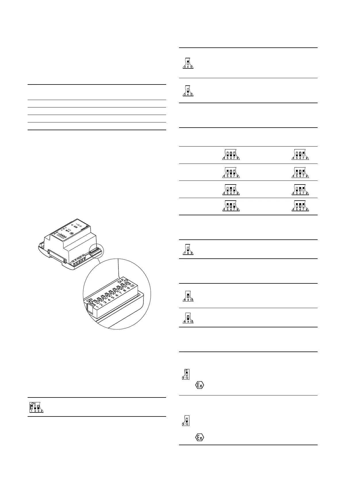
The module CU 212 has a 10-pole DIP switch in the bottom right
corner, see fig. 5.
Note: The controller must be off circuit to ensure the correct
configuration during start-up after change of the DIP switch
setting.
The DIP switch setting offers the following possibilities:
• selection of starting delay and automatic test run (switch 4),
• setting of stop delay (switches 5, 6 and 7),
• selection of automatic alarm resetting (switch 9),
• selection of automatic restarting (switch 10).
Fig. 5
Set the DIP switch as shown in fig. 5. Each individual switch (1 to
10) of the DIP switch can be set to position OFF or ON.
Note: The DIP switch must not be set to other switch
combinations than those described in this section.
Set the switches 1 to 10 as follows:
•Switches 1, 2 and 3, application type:
When the DIP switch setting is changed, the controller must
be switched off for at least 1 minute!
•Switch 4, starting delay and automatic test run
(only in the case of battery back-up):
When the DIP switch setting is changed, the controller must
be switched off for at least 1 minute!
• Switches 5, 6 and 7, stop delay:
When the DIP switch setting is changed, the controller must
be switched off for at least 1 minute!
•Switch 8:
When the DIP switch setting is changed, the controller must
be switched off for at least 1 minute!
•Switch 9, automatic alarm resetting:
When the DIP switch setting is changed, the controller must
be switched off for at least 1 minute!
•Switch 10, automatic restarting:
When the DIP switch setting is changed, the controller must
be switched off for at least 1 minute!
Pos. Description
Terminal
number
1 Float switch for common stop. 11-12
2 Float switch for start of the first pump. 21-22
3 Float switch for start of the next pump. 31-32
4 Float switch for high-level alarm. 41-42
TM04 2341 2308
This setting determines the actual application type
(parallel operation with 4 float switches, pages 25 and
26).
At this setting, the start-up is delayed within the range
from 0 to 255 sec. (random) after the electricity supply
has been switched on when the liquid level is
sufficiently high.
Automatic test run carried out every 24 hours.
After the electricity has been switched on, the pump will
start immediately when the liquid level is sufficiently
high.
No automatic test run.
The stop delay is the time from the stop signal is given until the
pump is stopped.
It must be ensured that the pump is not running dry.
0 sec. 60 sec.
15 sec. 90 sec.
30 sec. 120 sec.
45 sec. 180 sec.
Switch 8 has no function in connection with the actual
application (parallel operation with 4 float switches,
pages 25 and 26), but this setting must be maintained!
This setting ensures automatic resetting of alarm
signals to external alarm devices and the built-in
buzzer. However, an alarm signal will only be reset if
the cause of the fault no longer exists.
At this setting, the alarm signal must be reset manually
by means of the reset button (the reset button is
described in section 4.5).
This setting enables automatic restarting after the PTC
resistance/thermal switch of the motor has cut out the
pump. Restarting will not be carried out until the motor
has cooled to normal temperature.
When the pumps connected are used in explosion
hazard areas, switch 10 must not be in this
position!
At this setting, the pump must be restarted manually after
the PTC resistance/thermal switch of the motor has cut
out the pump. To restart the pump, push the ON-OFF-
AUTO selector switch into position OFF for a short period
(the ON-OFF-AUTO selector switch is described in
section 4.5).
When the pumps connected are used in explosion
hazard areas, switch 10 must be in this position!