English (US)
10
5.3 Motor direction of rotation
After the product has been wired and checked to ensure that all
components in the system, such as disconnect devices, magnetic
starters, pilot devices and motors, are properly connected, check
the motor direction of rotation as follows:
• For three-phase products only, momentarily energize the
motor to ensure that the direction of rotation is correct as
indicated by the arrow cast into the pump housing.
If direction of rotation is incorrect, interchange two wires at the
motor starter terminals T1 and T2.
5.4 Starting the pump
1. Install a coupling guard on coupled products.
2. Fully open the gate valve (if any) in the inlet line, and close
the gate valve in the outlet line.
3. Fill the inlet line with liquid and completely prime the pump.
4. Start the pump.
5. Immediately make a visual check of the pump and inlet pipe
for pressure leaks.
6. Immediately after the pump has reached full operating speed,
slowly open the outlet gate valve until complete system flow is
achieved.
7. Check the outlet pipe for pressure leaks.
8. If the pump is fitted with pressure gauges, open gauge cocks
and record pressure readings for future reference. Verify that
the pump is performing in accordance with the parameters
specified in the performance curves.
9. Check and record voltage, amperage per phase, and
kilowatts, if a wattmeter is available.
5.5 Voltage and frequency variation
The motor will operate satisfactorily under the following voltage
and frequency variations, but not necessarily in accordance with
the standards established for operation under rated conditions:
• The voltage variation must not exceed 10 % above or below
the rating specified on the motor nameplate.
• The frequency variation must not exceed 5 % above or below
the motor rating.
• The sum of the voltage and frequency variations must not
exceed 10 % above or below the motor rating, provided the
frequency variation does not exceed 5 %.
6. Storing and handling the product
See sections 3.3 Temporary storage after delivery, 9.2 Short-time
shutdown and 9.3 Long-term shutdown.
7. Product introduction
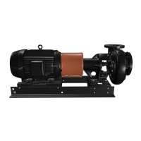
7.1 Applications
We recommend the L pumps for these applications:
• commercial and industrial cooling systems
– pumping both primary and secondary cooling water
• condenser water systems
• district cooling systems
• water distribution systems
• irrigation systems.
7.2 Pumped liquids
Clean, thin, non-aggressive liquids, not containing solid particles
or fibers. Do not pump liquids that will attack the pump materials
chemically.
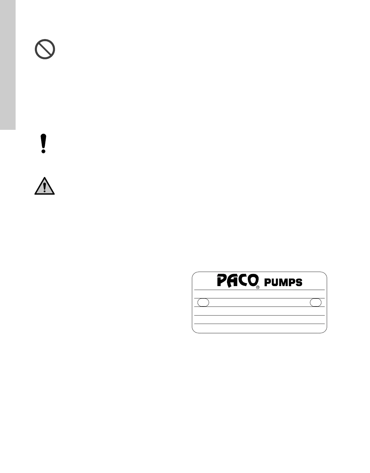
7.3 Pump identification
All pumps are identified by catalog and serial numbers. These
numbers are stamped on the pump nameplate, as shown in fig. 6,
affixed to the pump housing. Refer to these numbers in all
correspondence with Grundfos.
Fig. 6 Nameplate
Never check the motor direction of rotation unless
the pump and motor couplings have been
disconnected and physically separated. Failure to
follow this instruction can result in serious damage
to the pump and the motor if the direction of rotation
is wrong.
The pumps must not be operated while dry.
Use extreme caution that motors are energized only
momentarily to determine proper direction of rotation.
DANGER
Moving machine parts
Death or serious personal injury.
- Mount an approved coupling guard before
operating the product.
TM06 6128 0616
CAT#: 10-20707-130101-1741
STOCK#:
SER#: 97R12345
GPM: 234
TDH: 88
MFD BY GRUNDFOS CBS INC 34014412
IMP
DIA
5.11
:
LC_LCV_LF_LCS_1 language_US Eng.book Page 10 Thursday, August 24, 2017 4:08 PM