9
English (US)
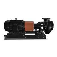
4.5.1 Motors
The motor control circuit must include the following components
in order to comply with the National Electrical Code:
Motor disconnecting device
• Install a motor disconnecting device that is capable of
disconnecting both the controller (motor starter) and the motor
from their source of power.
• Locate the disconnecting device in such a way that the
controller (motor starter) can be seen from the disconnecting
device. In all cases, the distance from the disconnecting
device to the controller must be less than 50 ft (15.24 m).
In most installations, the disconnecting device will be a circuit
breaker or fusible disconnect switch.
Motor short circuit and ground fault circuit interrupter
A short circuit and ground fault circuit interrupter is usually a
circuit breaker or fusible disconnect switch.
• Select the circuit breaker or fuse in accordance with section
430-52 and table 430-152 of the National Electrical Code.
Motor controller with overcurrent protection (magnetic
starter)
• Install these components in accordance with applicable local
and state electrical codes in addition to the National Electrical
Code.
4.5.2 Wiring
• Mount the control panel or the motor starter(s) close to the
pump to provide convenient control and easy installation.
• Wire panel or starter(s) to motor(s) and pilot device(s).
Wires to the motor(s) must be sized for at least 125 % of the
motor nameplate full load amps. We recommend AWG #16
Type THW stranded wire for wiring of pilot devices, such as
float switches.
• Check that the voltage, phase and frequency of the incoming
power source correspond to the voltage, phase and frequency
of the motor(s).
• Make sure that the starters are suitable for operating the pump
motors on the voltage, phase and frequency available.
5. Starting up the product
5.1 Priming
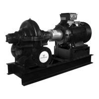
End suction pumps are non-self-priming and must be completely
primed, i.e. filled with liquid, before starting.
• If the pump will be operating with a positive inlet pressure,
prime it by opening the inlet valve and allowing liquid to enter
the pump housing. Open the air vents and make sure all air is
forced out of the pump by the liquid before closing the air
vents.
• Rotate the shaft by hand to free entrapped air from the
impeller passageways.
• If the pump will be operating with a suction lift, priming must
be accomplished by other methods. Use foot valves or
ejectors, or fill the pump housing and the inlet line manually
with liquid.
5.2 Pre-start checklist
Make the following inspections before starting your L pump:
1. Make sure the inlet and outlet pipes have been cleaned and
flushed to remove dirt and debris.
2. Double check the direction of rotation which must be
clockwise. Operating in reverse will destroy the impeller and
shaft.
3. Make sure all wiring connections to the motor and starting
device are in accordance with the wiring diagram.
4. If the motor has been in storage for a long time, either before
or after installation, refer to the motor instructions before
starting.
5. Check the voltage, phase and frequency with the motor
nameplate. Turn the impeller by hand to make sure it rotates
freely.
6. Tighten the plugs in the gauge and drain holes. If the pump is
fitted with pressure gauges, keep the gauge cocks closed
when they are not in use.
7. Check the inlet and outlet pipes for leaks, and make sure all
flange bolts are securely tightened.
DANGER
Explosive environment
Death or serious personal injury
- Observe the rules and regulations generally or
specifically imposed by the relevant responsible
authorities or trade organizations in relation to
running powered equipment in an explosive
environment.
Never run the pump dry in the hope that it will prime
itself. The result will be serious damage to the shaft
seals, pump wear rings and shaft sleeves.
Do not operate the product above the nameplate
conditions. This may damage the product.
LC_LCV_LF_LCS_1 language_US Eng.book Page 9 Thursday, August 24, 2017 4:08 PM