2. Use dial indicator to check hub circumference and
end face. Adjust the hub alignment according to
the measurements. The deviation of hub
circumference and end face mustn't exceed 0.05
mm. For hub flange diameter bigger than 250 mm,
the maximum deviation is 0.08 mm. Reinstall the
hub if the deviation exceeds the limit. Refer to
section Tightening torques for spacer coupling.
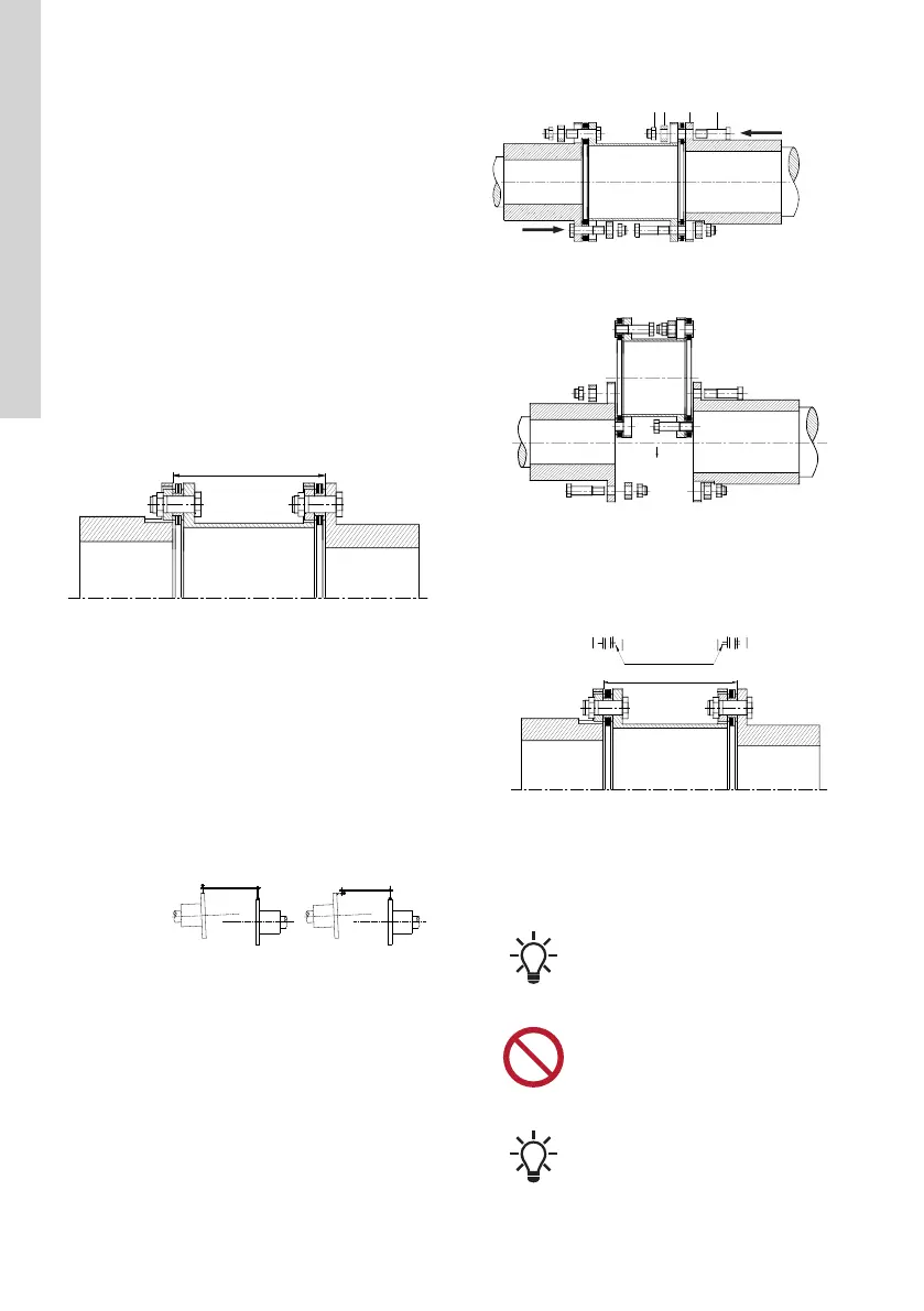
3. Place the motor and the pump in working position
and measure the distance F between the two hub
surfaces of the motor and pump. Take four
readings along circumference with 90° interval
and calculate the average value. Adjust the
position of the motor and pump until the value of F
meets the dimension Ls in the assembly drawing,
Ls is the distance between pump shaft end and
motor shaft end. The deviation should be from 0
mm to 0.4 mm.
TM082166
4. Choose one of the following methods that suits
best for the installation:
a. Use professional aligning apparatus.
b. Use the dial indicator to measure the deviation
of the circumference and the end face.
Determine the location of shafts by analyzing
the measurements, and then adjust the shafts
based on the results. See section on Accepted
misalignment.
In order to improve the precision, use two dial
indicators that locate equidistant to axis to
measure the deviation of the end face.
TM082161
5. Place the disc packs and the spacer between the
hubs, tighten with bolts, sleeves and self-locking
nuts or slotted nuts. The hexagon bolts (2) must
be installed next to flanges (8). The sleeves (4)
and the nuts (3) must be installed next to each
other. Reversion is prohibited.Refer to the figure
below.
TM082160
• With short shafts distance, pre-install the bolts
into spacer and then perform the step above.
TM082159
• The dynamically balanced coupling parts must
be installed according to the position mark (M)
on the coupling. Fasteners with the same
specification in the same set of coupling can
be replaced with each other.
TM082158
6. Tighten the nuts diagonally and evenly and make
sure the bolts won't rotate when tightening. Use
the torque wrench to achieve the required
tightening torque at least in two rounds. See
section on Torque.
Apply a little grease to the nut thread
before the installation.
Self-locking nuts can be used
repeatedly. But if the nuts can be freely
tighten to bolts manually or the nuts
have defects, the users mustn't use
them.
For slotted nuts, insert a cotter pin to
secure and make sure it won't loosen
when operating.
10
English (GB)