English (GB)
5
6. Megging
1. Disconnect the power supply.
2. Remove the terminal box.
See section 7.9 Replacing the terminal box.
3. Measure between terminals T1, T2, T3 and earth. As windings
are star-connected, fault in a winding will show when
measuring all terminals.
4. Replace the entire motor unit in case of fault.
See also measurement of winding resistances in section
8.4 Power module.
5. Fit the terminal box.
See section 7.9 Replacing the terminal box.
6. Switch on the power supply.
7. Start the pump.
7. Replacing hardware
Fig. 1 Antistatic service kit
7.1 Replacing the terminal box cover
1. Loosen the four screws (pos. 251d) and remove terminal box
cover (pos. 251b).
2. Clean the sealing faces of terminal box (pos. 251a) and the
terminal box cover.
3. Fit the terminal box cover and cross-tighten the screws. Make
sure that the position of the terminal box cover is correct in
relation to the control panel (pos. 290).
7.2 Replacing the battery
Applies only to the FM300 functional module.
1. Disconnect the power supply.
2. Remove the terminal box cover. See section 7.1 Replacing
the terminal box cover.
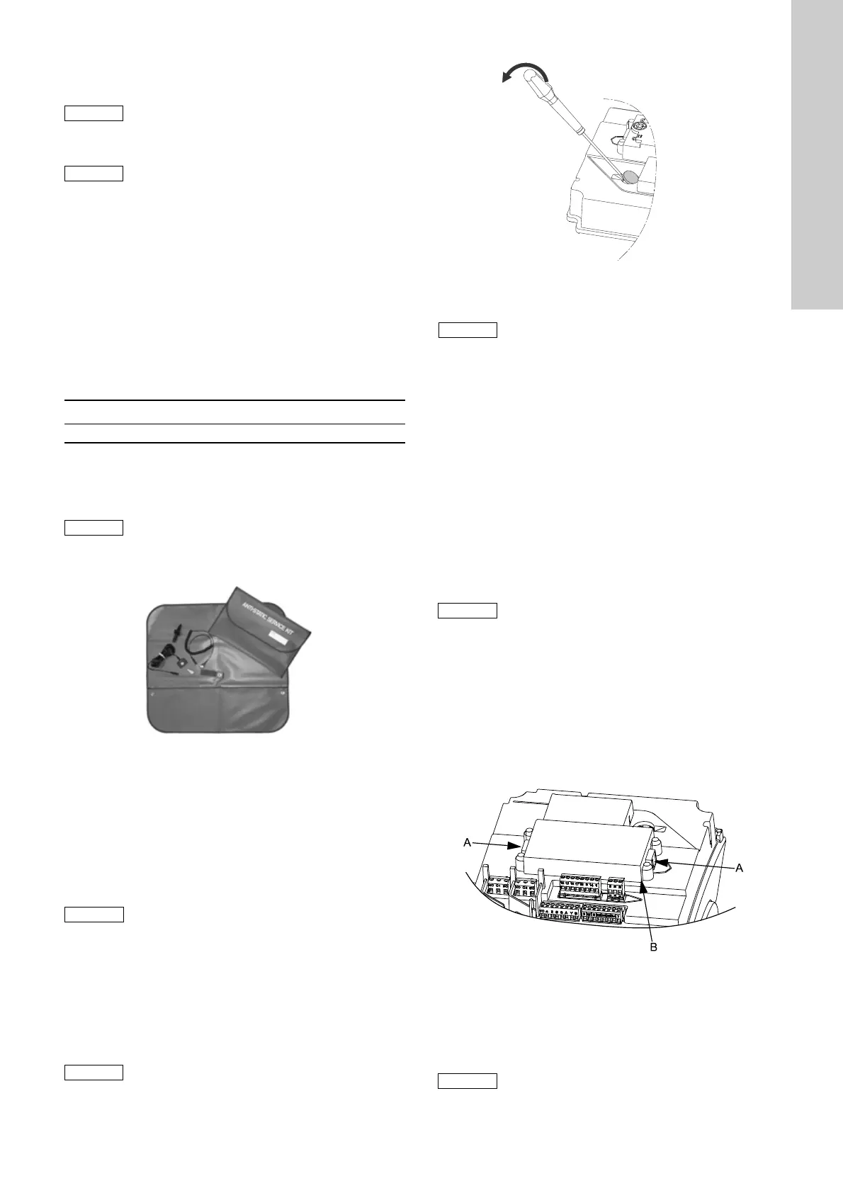
3. Insert a screwdriver under the battery (pos. 273b) and prise
the battery out of the isolation cover (pos. 277).
Fig. 2 Removing the battery
4. Insert the new battery with the positive pole upwards.
5. Press the battery home with a finger.
6. Fit the terminal box cover. See section 7.1 Replacing the
terminal box cover.
7.3 Fitting the antenna
1. Disconnect the power supply.
2. Remove the terminal box cover.
See section 7.1 Replacing the terminal box cover.
3. Remove blanking plug (pos. 252b) from the terminal box.
4. Fit union (pos. 291) in the terminal box.
5. Lead the antenna into the union from above and tighten the
top part (close to the wire).
6. Click the antenna wire onto the control panel (pos. 290).
The antenna wire is long enough to be fitted in both positions
of the control panel.
7. Fit the terminal box cover.
See section 7.1 Replacing the terminal box cover.
7.4 Replacing the control panel
1. Disconnect the power supply.
2. Remove the terminal box cover.
See section 7.1 Replacing the terminal box cover.
3. Press and hold in the two locking tabs (fig. 3, pos. A) while
gently lifting the control panel (fig. 3, pos. B, and pos. 290).
Fig. 3 Removing the control panel
4. Gently remove the plug for the control panel from functional
module (pos. 273).
5. Connect the plug for the new control panel to the functional
module.
6. Turn the control panel to the desired position (0 ° / 180 °).
An installation with MGE motors must not be
megged as this may damage the built-in
electronic parts.
Motor windings may, however, be megged if the
terminal box has been removed.
Never measure between two terminals.
Max. test voltage Max. leakage current [mA]
1000 VAC/1500 VDC 35
Always use an antistatic service kit when
handling electronic components. This will
prevent static electricity from damaging
components.
When unprotected, the component must be
placed on the antistatic cloth.
TM05 1590 3211
The control panel can be turned 180 °.
The old battery must be disposed off according
to the battery directive (2006/66/EC).
TM05 7021 0413
The new battery must comply with the battery
directive (2006/66/EC).
Make sure that the antenna wire is not sharply
bent or pinched when you fit the terminal box
cover.
TM05 5353 3612
Do not twist the flat cable by more than 90 °.

 Loading...