English (GB)
8
7.9 Replacing the terminal box
1. Disconnect the power supply.
2. Remove the terminal box cover.
See section 7.1 Replacing the terminal box cover.
3. Disconnect all relevant wires.
4. Remove screws (pos. 178) from terminal box (pos. 251a) and
gently lift the terminal box off the motor (pos. 150).
5. Fit the new terminal box on the motor. Make sure that the plug
connections are aligned.
6. Cross-tighten the screws of the terminal box.
7. Move relevant modules to the new terminal box according to
the section above.
8. Connect all relevant wires.
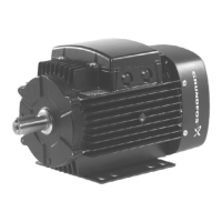
9. Transfer data from the nameplate of the old terminal box to
the nameplate of the new one.
Fig. 11 Transferring data to new nameplate
10. Fit the terminal box cover.
See section 7.1 Replacing the terminal box cover.
7.10 Replacing the stator housing
1. Disconnect the power supply.
2. Remove screws (pos. 178) and take terminal box (pos. 251a
and 251b) out of stator housing (pos. 150).
3. Remove the stator housing according the service instructions
of the system.
4. Install the stator housing in the system according to the
service instructions of the system.
5. Fit the terminal box on the stator housing and cross-tighten
the screws.
7.11 Replacing the fan
1. Disconnect the power supply.
2. Remove the terminal box. See section 7.10 Replacing the
stator housing.
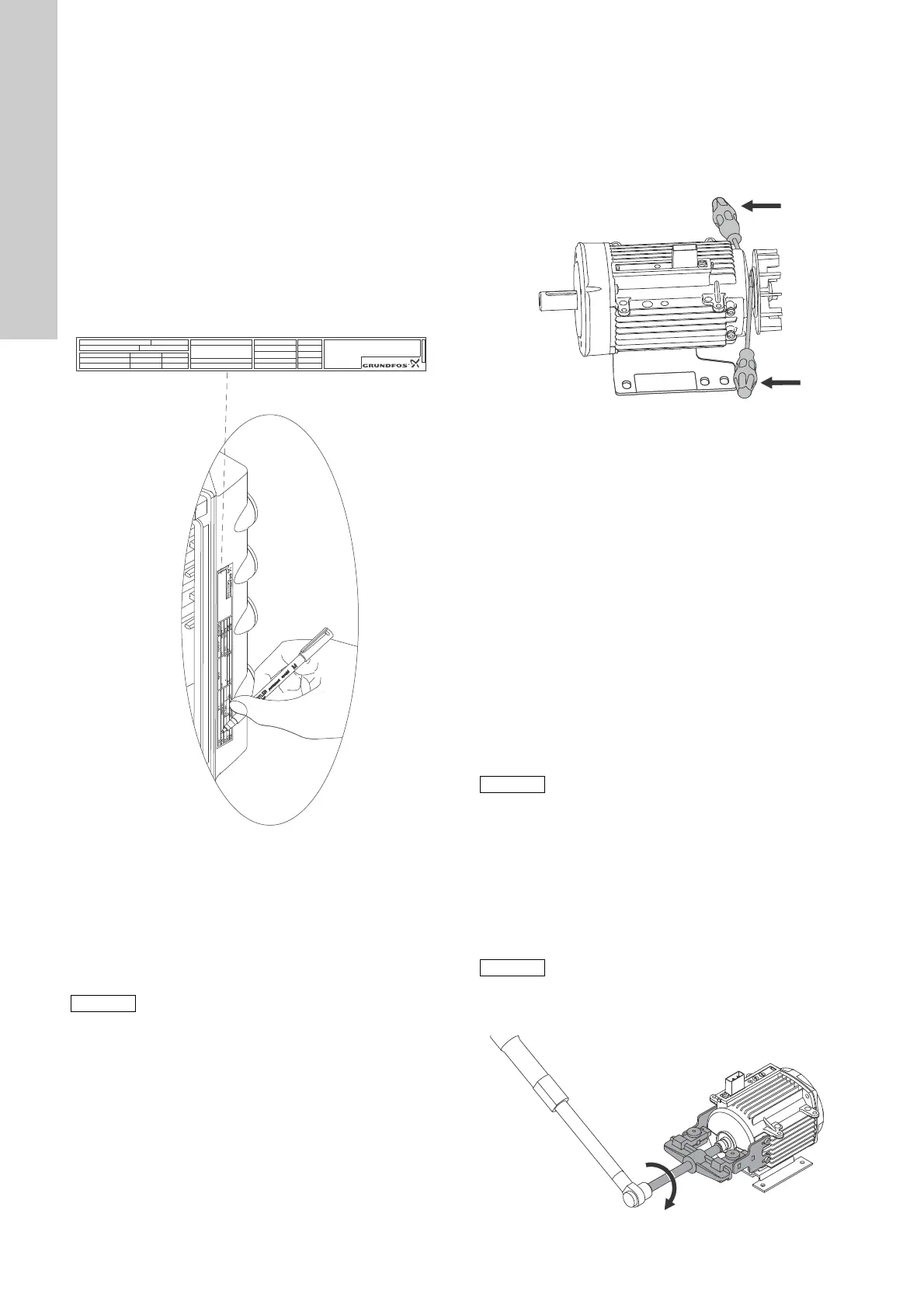
3. Remove screws (pos. 152) and lift off the fan cover (pos. 151).
4. Insert two screwdrivers close to the shaft and remove the fan
(pos. 156).
Fig. 12 Removing the fan
5. Push the fan on the shaft. Alternatively, gently knock the fan
onto the shaft (pos. 172) by means of a plastic hammer while
holding the drive end of the shaft against a solid surface.
6. Fit the fan cover on stator housing (pos. 150) and tighten
screws (pos. 152).
7. Fit the terminal box on the stator housing and cross-tighten
the screws.
7.12 Replacing the bearings
1. Disconnect the power supply.
2. Remove the stator housing from the terminal box.
See section 7.10 Replacing the stator housing.
3. Remove the fan. See section 7.11 Replacing the fan.
4. Remove seal rings (pos. 156c) from shaft (pos. 172).
5. Remove screws (pos. 185) holding the flange (pos. 156b).
6. Place the puller on the non-drive end of the stator housing
(pos. 150). See fig. 13.
7. Gently pull the rotor (pos. 172) out of the stator, holding rotor
and flange to prevent damage.
8. Remove gasket (pos. 156d) from the flange.
9. Wrap a piece of cardboard or similar material around the
magnetic rotor part to protect it against damage and dirt.
10. Put the flange in a vice with soft jaws.
11. Remove bearing (pos. 154) with a puller.
12. MGE 90: Remove locking ring (pos. 187) from the flange.
13. Remove the rotor from the flange and place the rotor in the
vice.
14. MGE 90: Remove locking ring (pos. 188) from the shaft.
15. Remove bearing (pos. 153) with a puller.
Fig. 13 Pushing the rotor out of the stator
TM05 6954
Support the terminal box when you remove the
motor.
Env.Type :
Serial no :
IP CL:
PF:
PB
FM
HMIEff
n max:
CIM
Wgt
:
DE
:
kg
NDE
:
T
amb
:
:
CA
V
~
P.C.
:
Made in Hungary
OUTPUT
VARIANT
INPUT
Type
:
P.N.
:
U
in
:
I
1/1 :
f
in
kW
Hz
P2
rpm
:::
:
:
:
:
o
DK - 8850 Bjerringbro, Denmark
TM05 7022 0413
Keep metallic dust away from the rotor as the
rotor is magnetic.
Do not tighten the vice on the bearing journal.
TM05 7027 0413

 Loading...