English (GB)
6
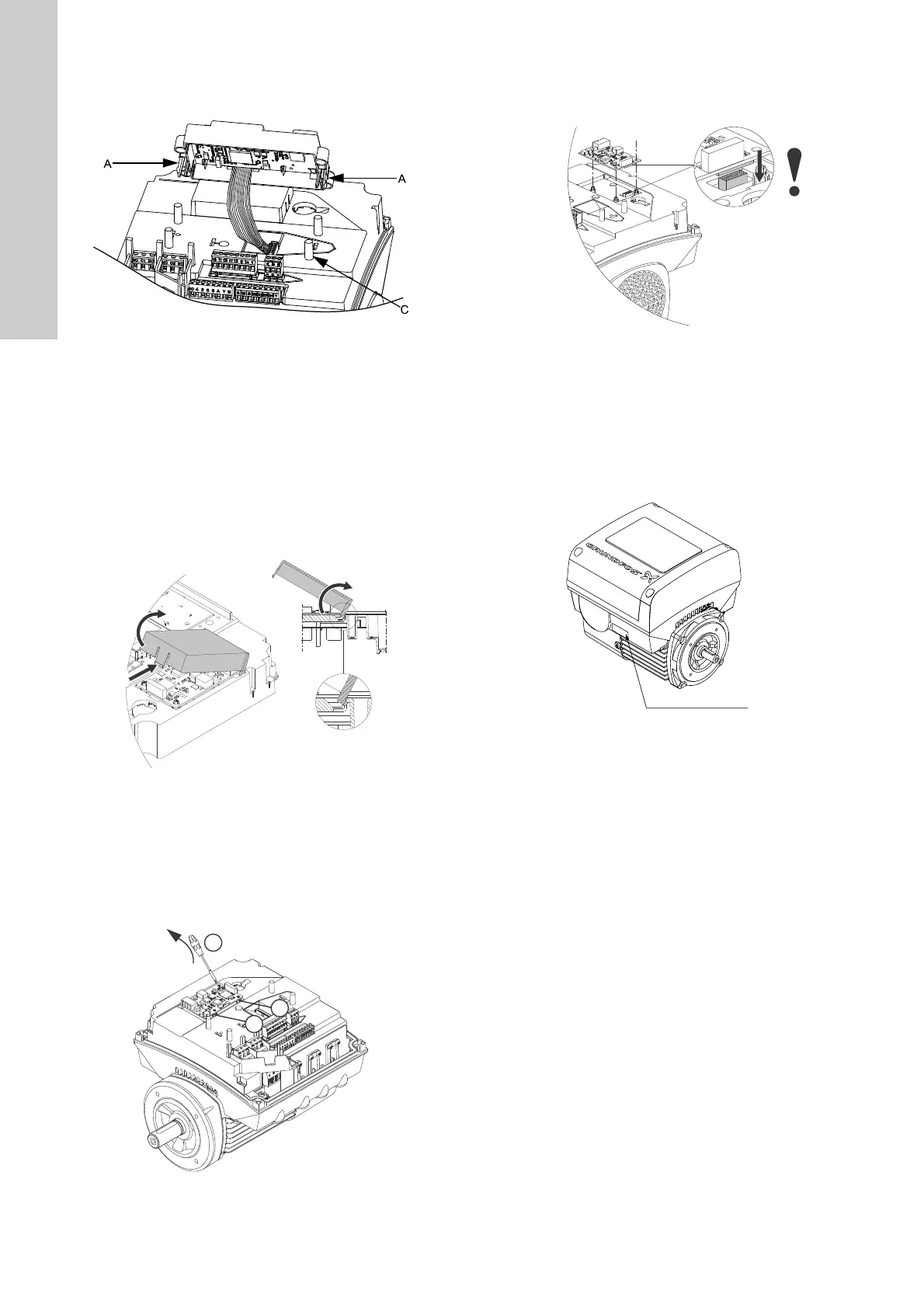
7. Position the control panel correctly on the four rubber pins
(fig. 4, pos. C). Make sure that the locking tabs (fig. 4, pos. A)
are placed correctly.
Fig. 4 Fitting the control panel
8. Fit the terminal box cover.
See section 7.1 Replacing the terminal box cover.
7.5 Replacing the CIM module
1. Disconnect the power supply.
2. Remove the terminal box cover.
See section 7.1 Replacing the terminal box cover.
3. Remove the plug connection for the CIM module.
4. Remove the cover (pos. 287) of the CIM module by pressing
the locking tab (fig. 5, pos. A) and lifting the end of the cover
(fig. 5, pos. B). Then lift the cover off the hooks (fig. 5, pos. C).
Fig. 5 Removing the cover of the CIM module
5. Remove the screw connecting the frame connection of the
CIM module to the functional module.
6. Insert a screwdriver at the three plastic holders and loosen
the CIM module from isolation cover (pos. 277). See fig. 6.
7. Gently lift the CIM module away from the isolation cover so
that the connecting plug is not damaged.
Fig. 6 Removing the CIM module
8. Fit the new CIM module by aligning it with the plastic holders
and the connecting plug. Press home the module using your
fingers.
Fig. 7 Align the CIM module with the connecting plug.
9. Fit the frame screw in the CIM module.
10. Fit the cover by leading the slits into the end with the plug
connection and clicking the locking taps onto the isolation
cover.
11. Press down the module using your fingers. Check that the
plug has been pressed home.
12. CIM 250 and CIM 270: Put the FCC label on the terminal box.
Fig. 8 Position of FCC label
13. Fit the terminal box cover.
See section 7.1 Replacing the terminal box cover.
TM05 5355 3612TM05 7029 0413TM05 6711 5012
TM05 7023 0413TM05 7028 0413

 Loading...