Do you have a question about the Grundfos MAGNA 32-60 and is the answer not in the manual?
Specifies acceptable liquids and warns against flammable liquids.
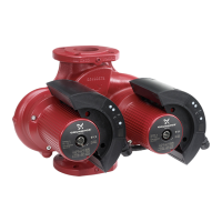
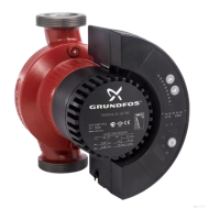
Details the required horizontal installation position for the GRUNDFOS MAGNA pump.
States the required supply voltage and frequency for the pump.
Details electrical connection requirements and safety precautions.
Lists functions controllable via the pump's built-in control panel.
Mentions functions available through the R100 remote control.
Details functions available via GENI and Relay expansion modules.
Explains available control modes like AUTOADAPT, Proportional, and Constant pressure.
Explains how to set the pump's setpoint for different control modes.
Lists functions for the Relay module.
Lists functions for the GENI module.
Explains how to change the pump's control mode using the control panel.
Describes setting the pump's setpoint via the R100.
Explains how to select operating modes (Stop, Min, Normal, Max) via R100.
Details how to view and reset fault indications on the R100.
Describes the alarm log feature on the R100.
Displays the actual setpoint and its relation to other settings.
Shows the current operating mode and how it was selected.
Displays the pump's current head and flow rates.
Shows the current operating speed of the pump.
Displays the temperature of the pumped liquid.
Shows the pump's current power input and accumulated consumption.
Displays the total accumulated operating hours of the pump.
Allows selection of control modes (AUTOADAPT, Proportional, Constant, Constant Curve).
Enables or disables the automatic night-time duty function.
Configures the temperature influence function for head adjustment.
Allows deactivation/reactivation of pump control panel buttons.
Configures the signal relay function for expansion modules.
Assigns a unique number to the pump for system identification.
Explains indicator light meanings and common fault causes with remedies.
| Head | Up to 6 m |
|---|---|
| Temperature Range | -10°C to +110°C |
| Max Pressure | 10 bar |
| Pipe Connection | G 2 |
| Pump Housing | Cast iron |
| Pressure Rating | PN 10 |
| Port-to-Port Length | 180 mm |
| Mains Frequency | 50/60 Hz |
| Rated Voltage | 230 V |
| Insulation Class | F |
| Pump Type | Circulator pump |
| Max Head | 6 m |
| Voltage | 230 V |
| Max Liquid Temperature | 110°C |
| Connection Size | G 2 |
| Approvals | CE |
| Power Consumption | 5 - 45 W |
| TF Class | TF 110 |