5 / 32
1.2 Type key
1.3 Configuration
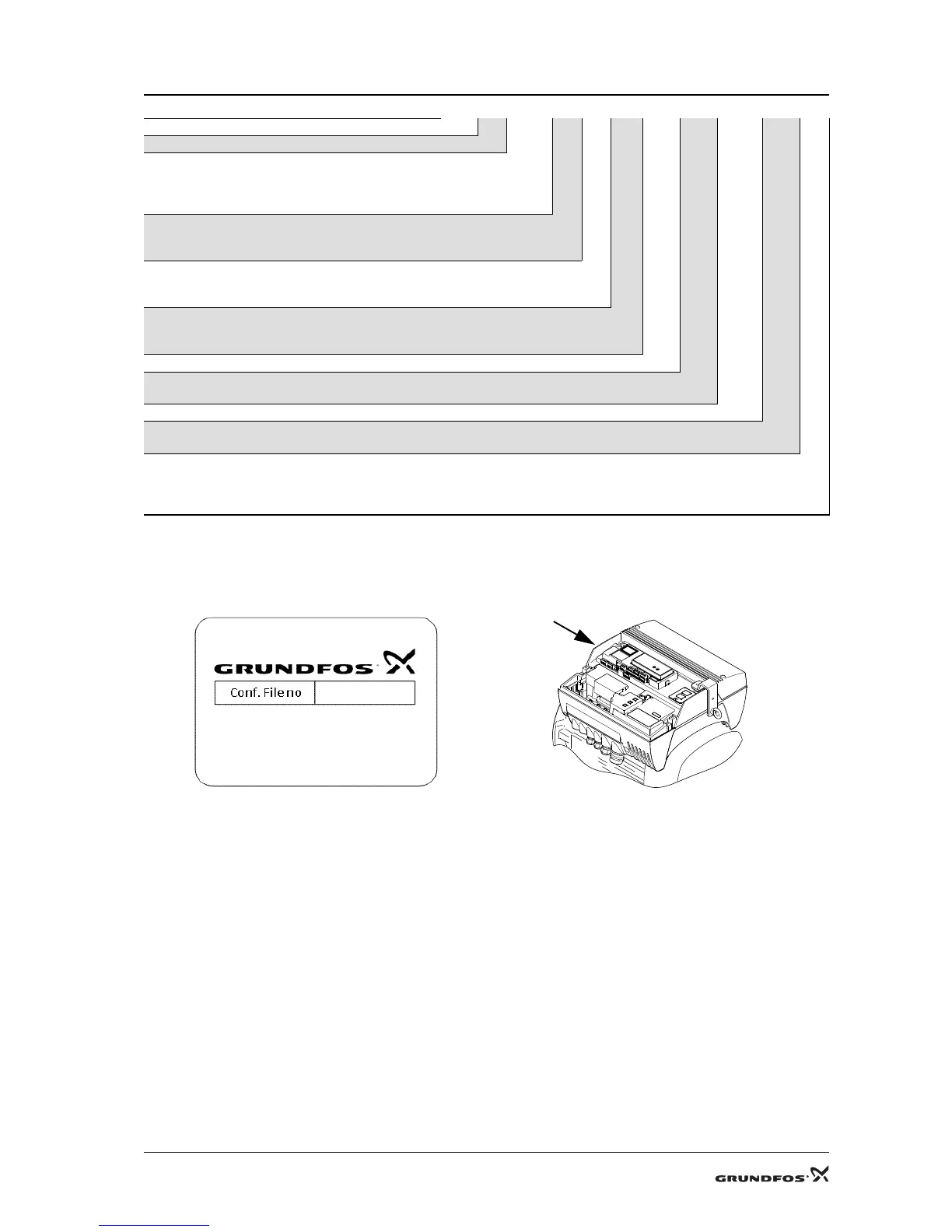
The terminal box is configured from factory for the application and the pump type the motor is to be used for. The
configuration file number appears from the terminal box configuration label which is placed inside the terminal box
on the frame of the control panel. See figs 5 and 6.
If the terminal box is replaced or mounted on another motor, it must be reconfigured. Contact Grundfos Service.
Example MG E 160 M D 2- 42 FF 300 -F 1
Motor Grundfos
Electronically controlled
Frame size according to IEC
(centre line height of shaft of foot motor) [mm]
160
180
Size of foot
M
L
Length of stator core
B
D
Number of poles
2
4
Diameter of shaft end [mm]
Flange version
FF (free-hole flange)
Pitch circle diameter, flange version [mm]
Model designation for motor
F
Efficiency class for standard motor
[ ] = not stated
1 = EFF 1 motor
2 = EFF 2 motor
TM04 2305 2308
TM04 2400 2508
Fig. 5 Configuration label Fig. 6 Position of configuration label
 Loading...