11 / 32
3.3 Operating conditions
Correct functioning of the MGE-F depends on these points:
Mains supply
• Check nameplate data, and measure the actual supply voltage with a digital voltmeter (true RMS).
• Check the earth leakage circuit breaker and the backup fuses. The MGE-F has no internal fuses.
Pump and motor load
• Check nameplate data, and measure the actual current consumption with a digital amperemeter (true RMS).
Do the pump and the MGE-F match?
External signals, for instance from another controller
• Check that the external signals are suitable for the MGE-F. See section 2.1 Wiring diagrams and signal terminals
and installation and operating instructions for MGE 160 and MGE 180.
• Check that terminals 2 and 3 are connected and that the MGE-F has been started via the control panel.
Sensors connected
• Check that the sensor measuring range matches the pump application.
• Check that the settings of the MGE-F match the sensors (current, voltage, minimum and maximum values)
(requires an R100).
Condensation
• Check whether condensation occurs in the terminal box. This may happen if the ambient temperature becomes
very low. The problem may be overcome by enabling the standstill heating function and by removing the drain plug
in the motor. See installation and operating instructions for MGE 160 and MGE 180.
Electromagnetic disturbances
• Check that the wiring complies with the EMC Directive. See installation and operating instructions for MGE 160 and
MGE 180.
Start-up, installation and operating settings via the control panel or the R100
• Check that the green indicator light on the control panel (or inside the terminal box) is on.
• Check that the settings in the INSTALLATION menu match the pump application (requires an R100).
The menu displays are described in detail in the installation and operating instructions for MGE 160 and MGE 180.
If the above points are according to the installation and operating instructions for MGE 160 and MGE 180 and the pump
application, but a fault still exists and the red indicator light is on, continue the fault finding in sections 3.5 Fault finding
using the indicator lights on the control panel and 3.6 Fault finding using alarm and warning codes.
3.4 Fault observations
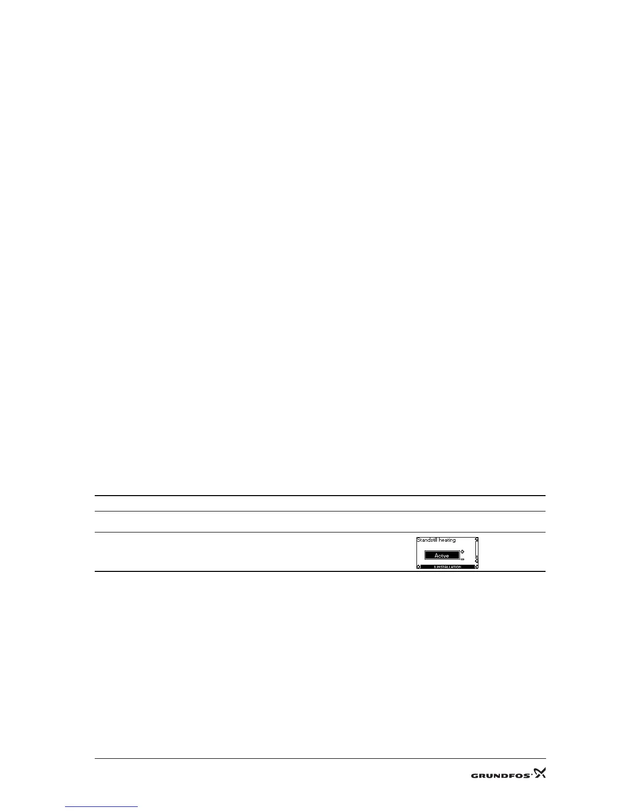
3.4.1 Condensation in the terminal box
Description
Condensation in the terminal box.
Explanation
During standstill, the motor temperature will fall below the dew point of the surrounding air.
Then the humidity in the air may condensate and settle on the surface of the terminal box.
Check/remedy
Activate Standstill heating with the R100 in the
INSTALLATION menu.

 Loading...